3D Scan Projection Wizard


  • Where to find them: 


    • Projector Palette / Right Mouse Click
    • Projector Palette /

    • Main Window / Extension Pack / Projectors / 


  • Shotcut:  non assigned


The 3D Scan Projection WIzard is designed to speed up the initial process of creating projections onto Models derived from 3D Scans.

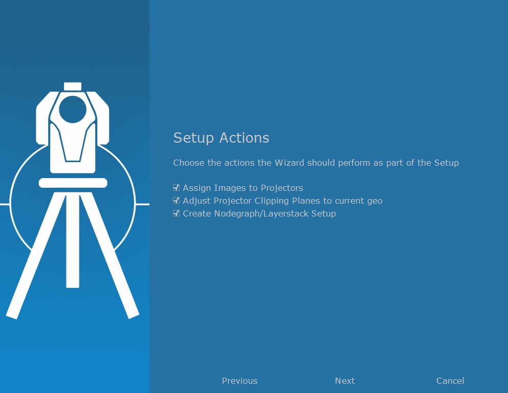
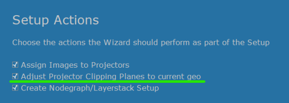
It will automate the following tasks for you


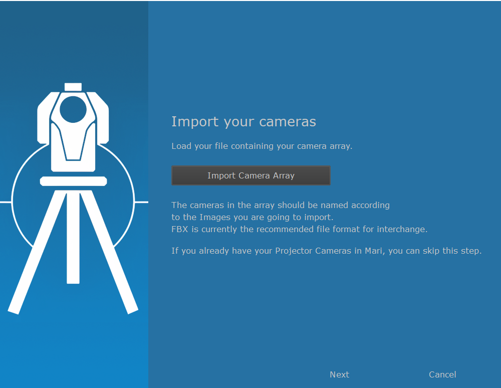
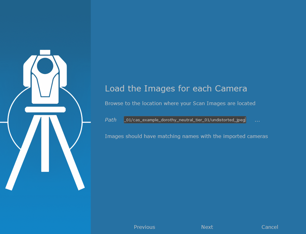
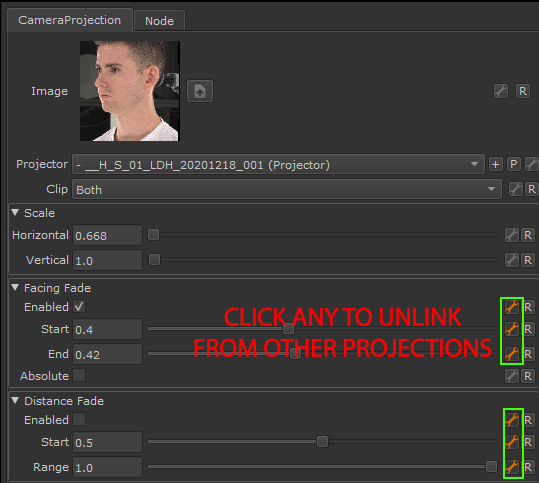
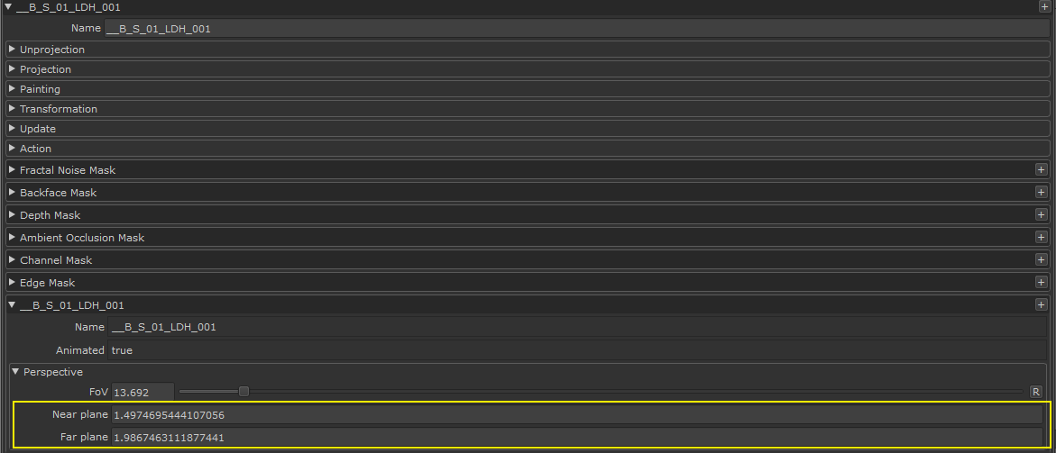
  • Setup Cameras (Projectors) with matching Images, correct DImensions etc. in the Mari Projectors Palette
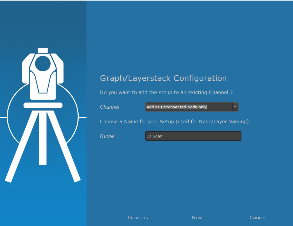
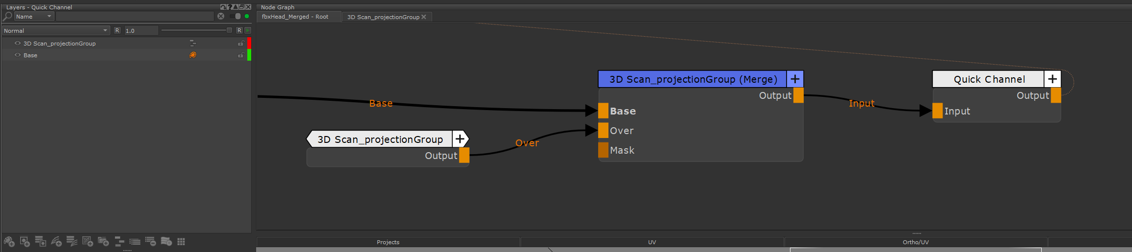
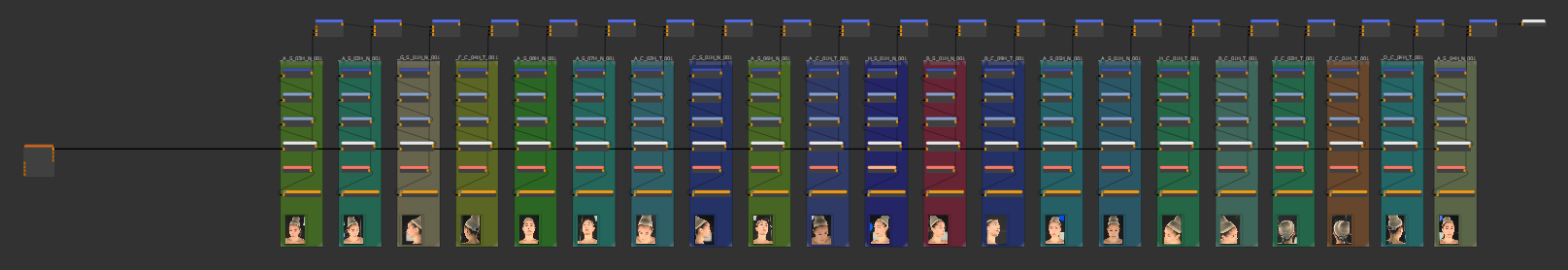
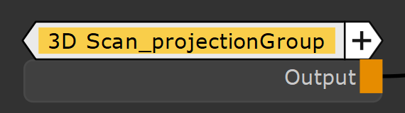
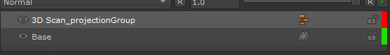
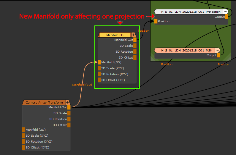
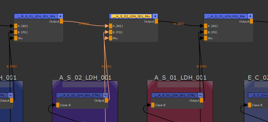
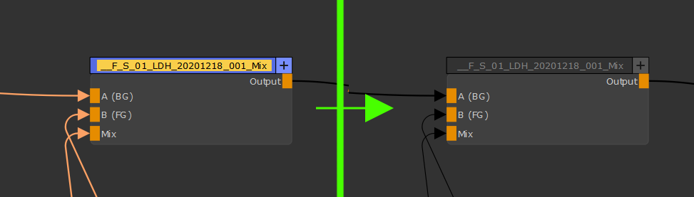
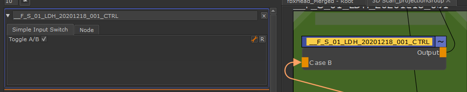
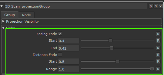
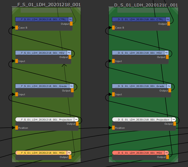
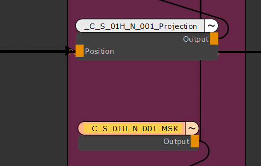
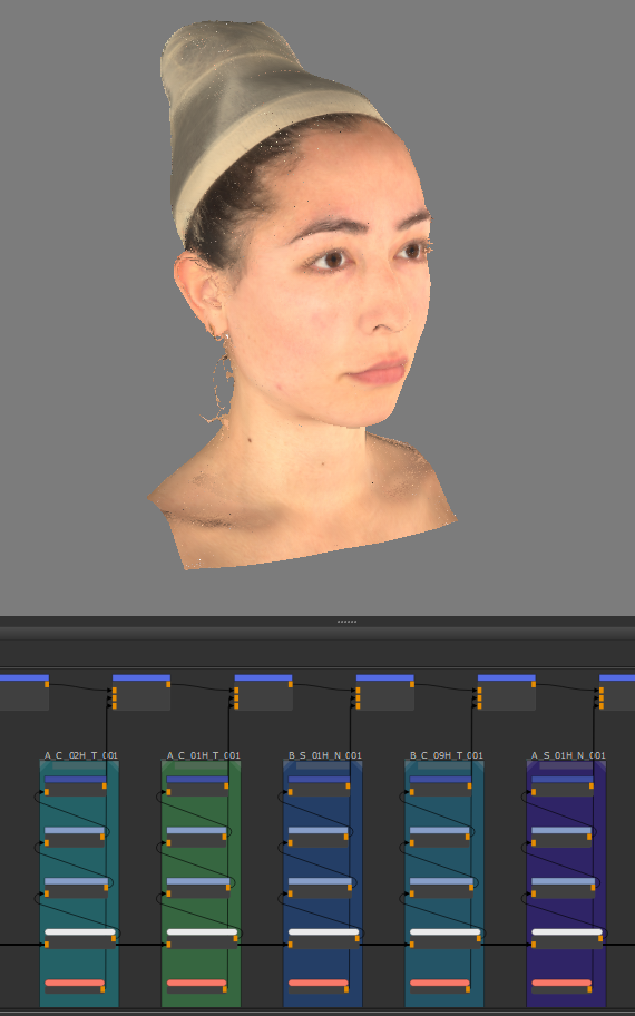
  • Create a non-destructive and live Projection Blend Setup as a Graph Group that can be added to your Nodegraph or Layerstack


You will still be required to do cleanup and proper blending/masking but the initial setup with this tool is easy and fast.


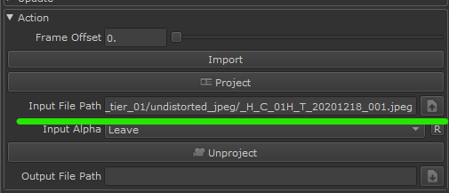
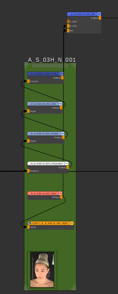
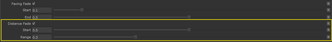
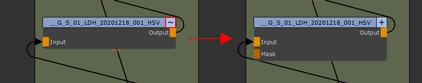
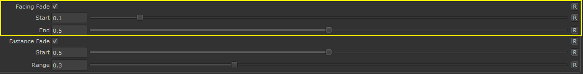
Example of an automatically created live projection setup, including camera projections, paintable Masks, Grading options etc.


It's WIzard Style interface should make it easy to follow the required steps however a more indepth explanation can be found further below.


Tutorial Video

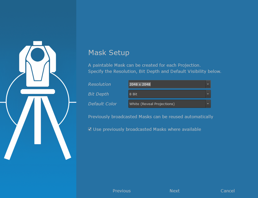
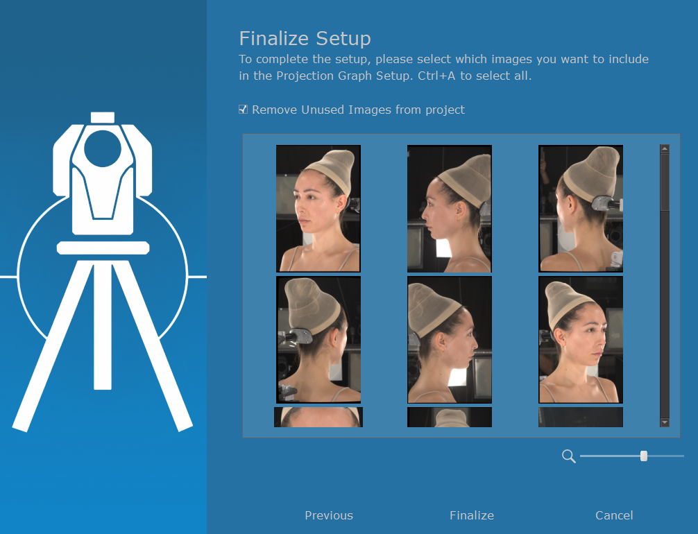
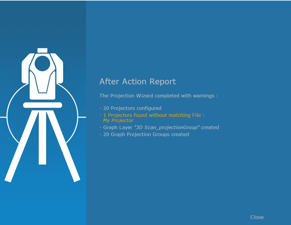
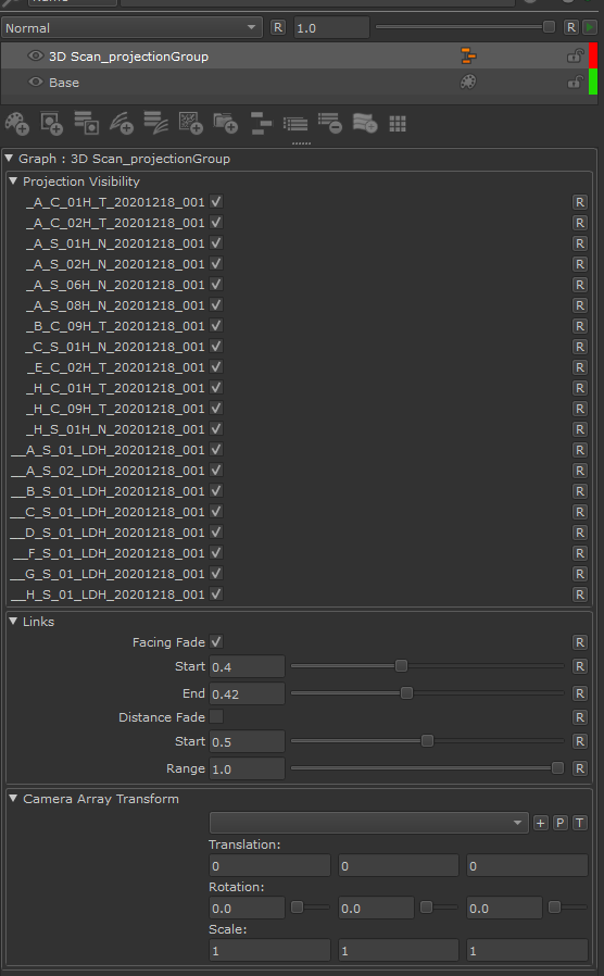
3D Scan Projection Wizard Dialog


The initial dialog will let you load in Cameras for your Projections. If you already have cameras loaded into Mari, you can skip this step.


Please note, images meant to be projected, need need to start with the same name as the imported Camera the image is associated to.

e.g.  _A_S_06H_N_20201218_001_CAM would be able to match onto _A_S_06H_N_20201218_001.jpg


When importing Cameras there are therefore some tips to consider:


    • The Alembic File Format when importing Cameras into Mari will assign the Shape Name of the Camera as Projector Name
    • The FBX File Format when importing Cameras into Mari will assign the Transform Name of the Camera as Projector Name


For advanced camera renaming options consider using the Multi Rename Projectors Tool


The Image dialog will let you select the Folder where the source images of your 3D Scan are located, that are meant to be projected


Please note, images meant to be projected, need need to start with the same name as the imported Camera the image is associated to.

e.g.  _A_S_06H_N_20201218_001_CAM would be able to match onto _A_S_06H_N_20201218_001.jpg


This Dialog sets the Colorspace and Bitdepth for the projected images.

If you choose to leave it at Automatic, the settings will be determined based on your OCIO Rules defined in the Mari File / Settings menu


  • Colorspace settings will be applied to the Projectors and the images loaded into the Image Manager.
  • Bit Depth will be applied to the Projectors only. 


This Dialog let's you define which actions the Wizard should perform


  • Setting up Projectors will assign corresponding images to Projectors "Input Paths", setup Camera Transforms & Colorspace

  • Auto adjusting each Projectors Clipping Plane to best suit your currently selected model


Auto Adjusting the Clipping Planes will greatly enhance convenience when working with the "Distance Mask" 
in the automatic Nodegraph creation


  • Creating a Nodegraph/Layerstack Setup will create a non-destructive, live Projection Setup in your Layerstack or Nodegraph


If you choose to only setup Projectors in this dialog, this will finish the Wizard and perform the setup.

If you choose to Create a Graph/Layerstack Setup, other wizard pages will appear


This page will only appear if "Create Nodegraph/Layerstack Setup" was ticked on in the previous page.


  • The Channel Setting determines if the Setup is created as a loose, unconnected Nodegraph setup or if added to an existing channel in a 
    Layerstack compatible way

  • The Name is an arbitrary Name that is used for Node/Layernaming, Image Manager Tab Naming etc.


This page will only appear if "Create Nodegraph/Layerstack Setup" was ticked in the previous Setup page.


Each Projection in the Nodegraph Setup will receive a unique paintable mask.

You can set the Resolution and Bitdepth of the Paint Nodes here.


The Default Color determines the default color a new mask gets created at. By default they are set to white, meaning all projections

are fully visible and you need to paint with a black brush to hide parts of a projection.


Setting it to Black by default, will hide all Projections by default and you need to paint with a white Brush to only reveal what you require.


The Use previously broadcasted Masks checkbox determines if the setup should automatically look for previousloy created Projection Setups and

inherit their Masks to the current one via Teleport Nodes.


This page will only appear if "Create Nodegraph/Layerstack Setup" was ticked in the previous Setup page.


On this dialog page you can select which images you want to include in the Non-destructive, live nodegraph projection setup.

If you are unsure which images will provide the best projection results when combined, select all (CTRL+A) .. you can easily remove projections later.


Remove Unused Images from Project will remove any unselected images from your project after this dialog closes, to keep your project file size smaller.


The After Action Report will provide a summary of all actions performed.

Any warnings such as Projectors that no Image was found for will be displayed here as well.


Wizard Results

Depending on which options were chosen during the Wizard Setup, you will get two elements:


Any Projector in the Projector Palette that had a matching Image found will be setup, ready for 

importing and projecting images.


Their Input File Path will be setup ...


.. as well as their Colorspaces


... and Transformations 


Depending if chose to add the Setup to an existing channel or not, you will end up with a single Graph Group Node in the Nodegraph ...


.. or a Graphgroup that is setup in a Layerstack comptable way


The same setup in the Layerstack (left) and Nodegraph (right)


Each Graph Group has 


  • Exposed Attributes on the Group Node

    • Visibility of each Projection is exposed
    • Projection Fadeoff options are exposed
    • The Transforms fo the Camera Array are exposed

Example of exposed Attributes here seen in the Layerstack


  • Subgraph

Graphgroups have a full subgraph. 

    • To open it in the Nodegraph, select the Node and press either "I" or "CTRL+ENTER"
    • To open it in the Layerstack, click on the orange graph icon 


The subgraph constructed by the Projection WIzard


Each Projection has an identical block setup. From top to bottom:

    1. _Mix Node to blend between the previous and current projection layer
    2. _CTRL Node to be able to toggle a projection on and off from the outside of the group
    3. _HSV Node to Color correct projections
    4. _Grade Node to Grade Projections
    5. Camera _Projection Node handling the camera projection
    6. A paintable Node_Msk to mask out the projection
    7. A Broadcast Node that broadcasts the Mask for future use in other setups
    8. A Thumbnail of the associated image


Workflow Tips & Tricks


You can easily transform the entire Camera Array by either selecting the main group node, the layer or the "Camera Array Transform" Node inside the Graph Group


Select any of the items below then proceed with the below description


You can either manually enter transform data into the node(s) ...


.. or with the node/layer selected, switch to the "Transform Object Tool" (Shift+T)


You can then transform the Camera Array via the Viewport Gizmo.
Press CTRL+SHIFT and click on a Scale Handle to scale uniformly.

Click on the Object to return to the main Object when done.


When switching to the Transform Gizmo, your Nodegraph/Layerstack will blank out. 
This is normal Mari behavior. Click on your Object or select your object in the object palette to return
to your Graph/Layerstack


To transform individual projections, independent of each other, add a new Manifold3D Node between the original Camera Array Transform manifold3D Node

and the projection you want to modify ..


.. then either manually enter Transforms into that new Manifold Node or use the Transform Selected Object with the Node

selected to enter Viewport Transform Mode.


To easily reorder projections


  • Select a any node of a Projection Block


  • Click on the left/right button in the Projectors Palette


You can move multiple blocks at once.


You have two ways to disable a Projection. This can be useful to turn off not needed projections or to debug which projections have undesirable effects.


  1. In the Graph Group select a _MIX Node and press "D" to disable the node


  2. In the Graph Group select a _CTRL Node and untick the checkbox in the Node Properties


    The Checkboxes in the _CTRL Nodes correspond to the checkboxes that are exposed on the Main Graph Group Node


By default the Main Projection Settings (e.g. Facing Fade etc.) of all Projections are linked together on the outside of the Group Node.


You can see they are linked by clicking on indidual _Projection nodes inside the Graph Group.
The Orange Button indicates the Attributes are exposed/linked.

To unlink a setting click on any of the orange Wrench Icons. 
After that you will be able to adjust all projections individually.


Click on a _Msk Node to paint a mask for a projection. 


The Active Paint Target by default has a lighter "Salmon" Color.


The Camera Projection Nodes used in the Nodegraph Setup allow you to fade out the result based on the distance from the camera.


The Start and End Position and the Range of the Mask are determined by the Clipping Plane of each Projector in the Projector Palette.


For best results and ease of working with the Distance Fade Sliders it is recommended to have tight clipping planes around your object.


The Scan Wizard can auto configure the Clipping Planes of each Projector to fit to the Bounding Sphere of the currently active object. 

This option can be found in the Projector Wizard Setup


You can extend the values past their maximum slider range by manually entering a value or placing your cursor in the numerical field of the slider and pressing the up/down keys.


In order to create Multi-Channel Projections, e.g. a matching Displacement and a Albedo, execute the WIzard twice, giving it separate Image Data.


Make sure to tick on the "Use previously broadcasted Mask" checkbox in the Wizard's Mask Setup Dialog, to have a shared setup for Masking.


When setting up a second or third Projection Setup, the WIzard will look for previously broadcasted Masks and auto connect them.


The Order of Projections on new Builds is also automatically inherited from the previous one.


For your convenience, HSV and Grade nodes are pre-added to the setup.


HSV and Grade nodes accept Mask nodes to limit their effect. Create a Paint Node (Hotkey "P") and attach it to mask the node effect.


Known Issues


Due to a bug in Mari 6.x, the "Facing Fade" Option on the Camera Projection Nodes does not correctly evaluate the facing ratio of the Projector Used.

The bug is scheduled to be fixed in Mari 7.0v1.


To work around this you will have to manually mask out problematic areas using the auto-generated paint nodes.