|
Shape Splatter 2D |
- Where to find it:
- Add Procedural Layer / Procedural / Extension Pack / Generators
 NodeGraph / Right Mouse Click / Add Nodes / Procedurals / Extension Pack / Generators
|
|
This Node is also available as a Triplanar Version |
Designed for creating random patterns, Splatter nodes allow Texture Bombing using a procedural shape

|
|
It is recommended to cache this node or attach a bake point after you are done tweaking it to keep its performance impact low |
|
Video |
|
Pattern Engine |
Pattern Engine Overview
This Node is part of a collection of Nodes making up the Pattern Engine:
- Pattern Generator X1 2D
- Pattern Generator X1 Triplanar
- Pattern Generator X4 2D
- Pattern Generator X4 Triplanar
- Symmetry Pattern X1 2D
- Symmetry Pattern X1 Triplanar
- Splatter X1 2D
- Splatter X1 Triplanar
- Splatter X4 2D
- Splatter X4 Triplanar
- Shape Splatter 2D
- Shape Splatter Triplanar
- Circular Pattern Generator X1 2D
- Circular Pattern Generator X1 Triplanar
|
Node Overview |

|
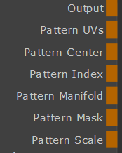
Node Ports |
- Output
The Default Output
- Pattern UVs
Outputs the UV coordinates of the cells
|
|
Additional Information such as pattern rotation is encoded in the Blue and Alpha channel that might make this output appear transparent. The UV information is unaffected. |
- Pattern Center
Outputs the center UV coordinate for each cell as a uniform value across the entire cell
- Pattern Manifold
Outputs Manifold Data from the node that can be used to drive other nodes.
A simple example of a Pattern Generator Node driving another node via the Manifold Output
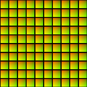
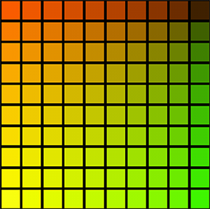
- Pattern Index
Outputs a R,G,B packed Index
- R - Row Index
Multiplies the normalized Row Number (0.0 - 1.0) against the result.
Each row will have a different value this way
- G - Column Index
Multiplies the normalized Column Number (0.0 - 1.0) against the result
Each column will have a different value this way
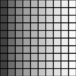
- B - Pattern Index
Multiplies the normalized Cell Number (0.0 - 1.0) against the result
Each cell will have a different value this way
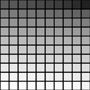
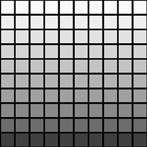
- Pattern Scale
Change the Value of each Cell based on the Cell scale, defined in the size group
Evaluated are Random Size X/Y, Random Scale,Random Scale Map, Normal Map
Example of Scale Output
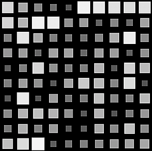
- Pattern Mask
Outputs the pure pattern result as a mask without the Background Color applied
- Pattern Random
Outputs the random signal used inside the node to randomize elements
- Manifold UV
Allows you to overwrite the UV Settings of the Node with a manifold node
- Seed
Randomization of Pattern
- Pattern Specific 1
An option to change the look of the generated Pattern. Varies based on Patttern. Overwrites Pattern Specific 1 Slider (Pattern Group) if mapped,.
- Pattern Specific 2
An option to change the look of the generated Pattern. Varies based on Patttern. Overwrites Pattern Specific 2 Slider (Pattern Group) if mapped,.
- Amount
Allows setting the Amount of Cells via a Nodegraph Input.
Will overwrite the Amount X and Amount Y Sliders.
Separate values can be fed to X and Y by specifying different values for Red and Green channel of the attached node stream
Allows for setting a Pattern Background. Fill Background needs to be turned on in the Color Group
|
Node Properties |
MAIN TAB
- Random Seed
By modifying the Random Seed, different looks can be achieved with the otherwise same settings.
- Amount Multiplier
A multiplier on the amount of Cells generated. Each cell is processed independently with the given settings (Position, Rotation etc. etc.)
- Amount X
Amount of cells generated horizontally. Each cell is processed independently with the given settings (Position, Rotation etc. etc.)
- Amount Y
Amount of cells generated vertically. Each cell is processed independently with the given settings (Position, Rotation etc. etc.)
- Pattern
Determines what pattern is used to fill each cell.
Options are
- One of 23 procedurally generated Patterns
For a complete overview of all procedural patterns visit the Shape Node Help
- Pattern Specific 1
An Option to change the look of procedurally generated Patterns. Varies based on Patttern
- Pattern Specific 2
An Option to change the look of procedurally generated Patterns. Varies based on Patttern
- Pattern Size
Determines the size of the procedurally generated Pattern within a cell.
Please note this works together with any size/scale specified in the Size Group.
- Pattern Rotate
Determines the rotation of the procedurally generated Pattern within a cell
- Pattern Alpha Intensity
Determines the processing of the Alpha Channel of a procedurally generated pattern.
Example of reducing the Alpha Intensity from 1 to 0 on a large Hemisphere pattern
- Pattern Repeat U
Repeats the pattern or input image x-amount of times horizontally in each cell.
Example of increasing Pattern Repeat U
on a 'Gaussian' Pattern
- Pattern Repeat V
Repeats the pattern or input image x-amount of times vertically in each cell.
- Pattern Random X
Randomly horizontally offsets the Pattern or Input Image within each cell
This is useful to have a more random look when using tileable textures
Example of randomly offsetting a tileable texture in X and Y
- Pattern Random Y
Randomly vertically offsets the Pattern or Input Image within each cell
This is useful to have a more random look when using tileable textures
- Invert Pattern
Invert pattern or Input Image
- Blend Mode
The Blend Mode used to overlay a cell over other cells
Example of different effects achieved by changing the blend mode
- Random Rotation
Applies a random rotation in 90 degree increments
- Keep Direction
If on, Random ROtation will rotate in 180 degrees to avoid changes of directions when using patterns that have a directionality
(e..g wood grain or brushed metal)
The Pattern Crop options allow to 'cut' the edges of a patterns or input images, allowing even more variation
Example of using the Pattern Crop to generate a triangle from a square
- Top
Control the Crop from Top to Bottom per Shape
- Bottom
Control the Crop from Bottom to Top per Shape
- Left
Control the Crop from Left to Right per Shape
- Right
Control the Crop from Right to Left per Shape
- Rotate
Rotate the Crop 'Frame' around its center
- Scale
A uniform scale factor.
|
|
If Pattern is set to a procedural pattern, scale works together with Pattern Size. Set both to 1.0 for 100% Scale |
- Size X
The horizontal size of each cell
- Size Y
The vertical size of each cell
- Random Size X
Mix Factor for size randomization in X for each cell.
Positive Values (0 - 1) will squash the cells along X.
Negative Values (-1 - 0) will stretch the cells along X.
- Random Size Y
Mix Factor for size randomization in Y for each cell.
Positive Values (0 - 1) will squash the cells along Y.
Negative Values (-1 - 0) will stretch the cells along Y.
- Random Scale
Mix Factor for uniform scale randomization.
Positive Values (0 - 1) will reduce the size of the cells randomly.
Positive Values (0 - 1) will increase the size of the cells randomly.
- Position Random X/Y
Randomly offset the Cell Positions along X and Y.
|
|
Higher Position Random Values will require a higher Layer Cutoff Value, which in turn reduces performance. Often times the same look can be achieved with a lower Position Random Value |
- Global Offset X/Y
Applies a global offset of the generated Pattern (all cells) along X or Y
- Rotation
Applies a rotation to each cell
- Global Rotation
Rotates the end result of the Pattern Generation. (globally, instead of per cell)
- Rotation Pivot Centered
Controls the Rotation Pivot for the Global Rotation Slider.
If ticked on, the Pivot sits at the center of each UDIM (0.5,0.5)
If ticked off, the Pivot sits at U/V 0.0 of UDIM 1001
- Rotation Random
Applies a random rotation to Cells
- Rotation Steps
Determines the freedom of the Rotation Random.
WIth a value of 360, Rotation Random will rotate cells freely from 0 to 360 degrees.
With a value of e.g. 90, Rotation Random will rotate cells in a range from 0 to 90 degrees.
- Mask Random
Randomly hides Cells
- Noise Type
Determines the Noise Type used for hiding cells when using Mask Random.
- Noise Seed
Randomizes the Noise Type used for hiding cells when using Mask Random
Shape Masking applies a mask to all cells of the Node. The Mask is applied in binary mode - a cell is either fully visible or hidden.
Other than for example using a Probability Mask attached to the Node Input Port, a Mask will never "cut through" a cell.
- Use Shape Mask
Activate Shape Mask Mode
- Shape Mask
The Image to use as Shape Mask
- MipMap Blur
A blur applied to the Shape Mask Image
- Shape Threshold
The value of the map representing the pivot point between "hidden" and "visible"
- Mask Repeat
THe number of times the Mask Image is repeated
- Mask Repeat U
The number of times the Mask Image is repeated horizontally. Multiplies against the "Mask Repeat"
- Mask Repeat V
The number of times the Mask Image is repeated vertically. Multiplies against the "Mask Repeat"
- Mask Rotation
Rotation of the Mask Image
- Rotation Pivot Centered
If on, rotation is evaluated against the center position (0.5 / 0.5) of the UVs.
If a 2D Node is used (as opposed to a triplanar node), this will mean a unique rotation pivot in the center of each udim.
- Mask Offset U/V
Translation values for the Mask in U and V
- Layer Cutoff
The Layer Cutoff determines the number of iterations and radius around each cell the node runs through before it stops calculating.
If you are experiencing Seams this might be the reason
|
|
Higher Layer Cutoff Values reduces performance ! Keep this value as low as possible without seeing seams |
To better understand this behavior and to anticipate consider this:
- By default each cell is generated in a grid pattern at a scale of 1.
- Each cell has an internal position of 0.0 for its own coordinate system
If you change the position of a cell from its original position of 0.0/0.0 the Layer Cutoff needs to be increased
for a wider sample radius. So for example
- adding a Random Position Value of 1.0/1.0 means we need to sample up to 1 additional cell around the original cell.
- We need to increase the Layer Cutoff to at least 2
- adding a Random Position Value of 2.0/2.0 means we need to sample up to 2 additional cell around the original cell.
- We need to increase the Layer Cutoff to at least 3
If you change the scale of a cell from its original scale of 1.0 the Layer Cutoff needs to be increased
for a wider sample radius. So for example
- Changing the Scale to 2 means we need to sample 1 additional cell around the original cell.
- We need to increase the Layer Cutoff to at least 2
- Changing the Scale to 4 means we need to sample 3 additional cell around the original cell.
- We need to increase the Layer Cutoff to at least 4
- Attenuation
Attenuation lowers the value of layers in the background successively for each Layer ID until it reaches a value of 0
If ticked on, the Pattern will be generated over the Background defined in the Background Color or the background attached to the Background Node port
- Background Color
The Background Color for the Pattern if Fill Background is ticked on. The Background Color is ignores if something is attached to the Background Node port
- Tint
Tint the result of the Pattern Generation with the specified color. Mutliplies the specified color against the result of the computation.
- Value Offset
Adds or subtracts the specified value from each layer of the pattern computation, lightening or darkening the output.
- Opacity
Set the Opacity for each cell
- Random Hue Multiplier
Affects how much the Hue is randomized in between cells
- Random Hue Min/Max
Sets the Min and Max Range for Random Hue changes in between cells
- Random Saturation Multiplier
Affects how much the Saturation is randomized in between cells
- Random Saturation Min/Max
Sets the Min and Max Range for Random Saturation changes in between cells
- Random Luminance Multiplier
Affects how much the Luminance is randomized in between cells
- Random Luminance Min/Max
Sets the Min and Max Range for Random Luminance changes in between cells
- Random Opacity Multiplier
Affects how much the Opacity is randomized in between cells
- Random Opacity Min/Max
Sets the Min and Max Range for Random Opacity changes in between cells
The Settings found in the Output Alphas Group determine how transparency of cell content is treated in the additional Output Ports of the Node
(Pattern UVs, Pattern Center, Pattern Index, Pattern Manifold and Pattern Scale)
- UVs premultiply
Premultiplies the transparency of cell content returned on the Pattern UVs output Port
- Center premultiply
Premultiplies the transparency of cell content returned on the Pattern Center output Port
- Index/Manifold premultiply
Premultiplies the transparency of cell content returned on the Pattern Index and Pattern Manifold output Ports
- Scale premultiply
Premultiplies the transparency of cell content returned on the Pattern Scale output Port
- Random premultiply
Premultiplies the transparency of cell content returned on the Pattern Random output Port
|
Tip |
If you are seeing seams in your pattern try raising the Layer Cutoff in the Layering Group.
|
|
Higher Layer Cutoff Values reduces performance ! Keep this value as low as possible without seeing seams |