|
Circular Pattern Generator X1 Triplanar |
- Where to find it:
- Add Procedural Layer / Procedural / Extension Pack / Generators
 NodeGraph / Right Mouse Click / Add Nodes / Procedurals / Extension Pack / Generators
|
|
This Node is also available as a 2D Version |
The Circular Pattern Generator allows you to create complex patterns using either an Input Image or a procedural Pattern.
|
Video |
|
Pattern Engine |
Pattern Engine Overview
This Node is part of a collection of Nodes making up the Pattern Engine:
- Pattern Generator X1 2D
- Pattern Generator X1 Triplanar
- Pattern Generator X4 2D
- Pattern Generator X4 Triplanar
- Symmetry Pattern X1 2D
- Symmetry Pattern X1 Triplanar
- Splatter X1 2D
- Splatter X1 Triplanar
- Splatter X4 2D
- Splatter X4 Triplanar
- Shape Splatter 2D
- Shape Splatter Triplanar
- Circular Pattern Generator X1 2D
- Circular Pattern Generator X1 Triplanar
|
Node Overview |
|
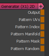
Node Ports |
- Output
The Default Output
- Pattern UVs
Outputs the UV coordinates of the cells
|
|
Additional Information such as pattern rotation is encoded in the Blue and Alpha channel that might make this output appear transparent. The UV information is unaffected. |
Example of using the Pattern UVs with an image Node
- Pattern Index
Outputs a R,G,B packed Index
- R - Cell Index
Outputs a unique value per cell
- G - Ring Index
Outputs a unique value per ring
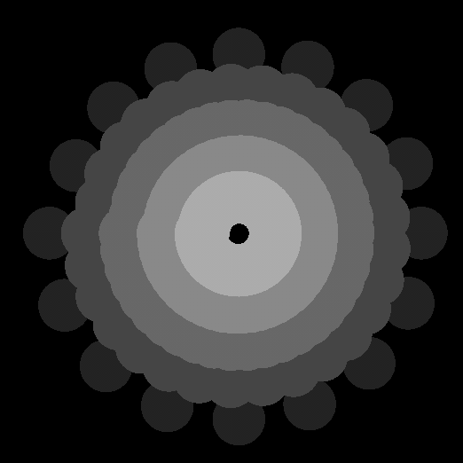
- B - Pattern Index
Outputs a unique value per angle inside the circle.
The value will be identical per angle across all rings, but unique per slice of the circle.
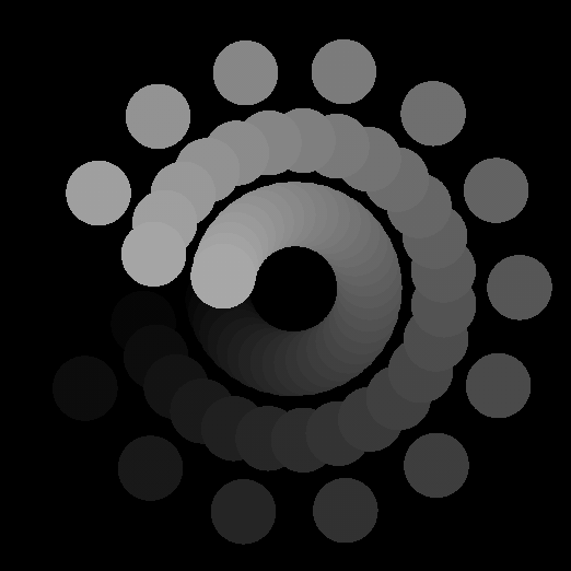
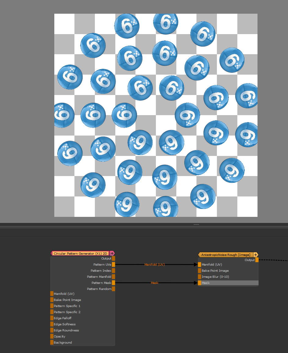
- Pattern Manifold
Outputs Manifold Data from the node that can be used to drive other nodes.
A simple example of a Pattern Generator Node driving another node via the Manifold Output
In the below example a HDRI is placed inside the Image Node.
You can see how the Manifold Data forces a radial image, resampling each cell of the Pattern Generator with
a value from a row of the HDRI
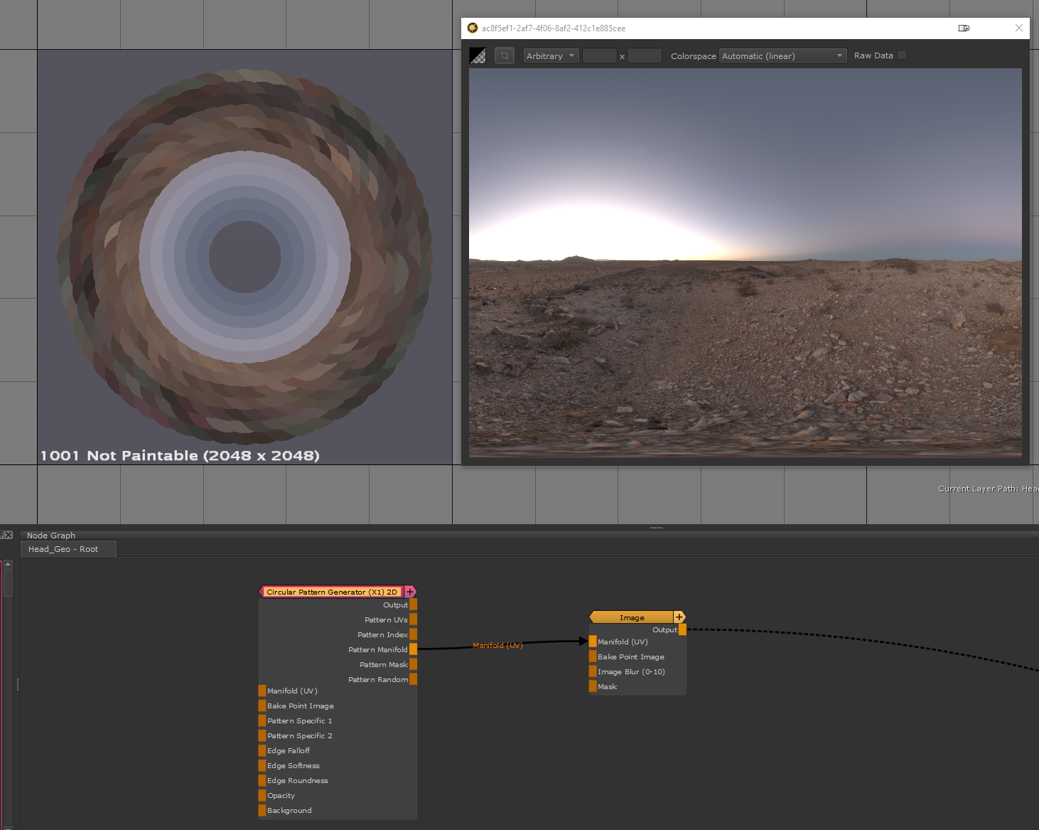
- Bake Point Image
![]()
The Bake Point Image Port allows you to feed data into the Node from upstream nodes that have been baked via a bake point into the Node.
When the node is evaluated, the Bake Point attached to the Port will be sampled and the UDIM 1001 Image will be transferred into
the Image Attribute of the Node.
This allows you to create patterns and textures via a nodegraph and use them directly inside this node with an element of non-destructivness
Example of using a Nodegraph and a Bake Point to dynamically feed a Pattern Generator Node with Node Inputs
- Pattern Mask
Outputs the pure pattern result as a mask without the Background Color applied
- Pattern Random
Outputs the random signal used inside the node to randomize elements
- Manifold UV
Allows you to overwrite the UV Settings of the Node with a manifold node
- Pattern Specific 1
An option to change the look of the generated Pattern. Varies based on Patttern. Overwrites Pattern Specific 1 Slider (Pattern Group) if mapped,.
- Pattern Specific 2
An option to change the look of the generated Pattern. Varies based on Patttern. Overwrites Pattern Specific 2 Slider (Pattern Group) if mapped,.
- Edge Falloff
Allows you to overwrite the Edge Falloff Attribute in the Pattern Group
- Edge Softness
Allows you to overwrite the Edge Softness Attribute (Pattern Group) with a Node Connection
- Edge Roundness
Allows you to overwrite the Edge Roundness (Pattern Group) Attribute with a Node Connection
|
|
Any value fed in through the Edge Ports on the Node is still multiplied against the corresponding Edge Slider in the Texture Groups of the Node. |
Allows changing the opacity of the Pattern with a Node Input.
Can be controlled via the Opacity Intensity Slider in the Color Group.
Allows for setting a Pattern Background. Fill Background needs to be turned on in the Color Group
- Manifold 3D
When mapped the world space position the node uses to calculate the projection is supplied by the port.
This can be used for example to apply warping to the projection using Manifold Nodes
- 3D Rotation (XYZ)
When mapped the red channel of the attached connection is used to drive the Rotate X Attribute,
the green channel the Rotate Y Attribute and the blue channel the Rotate Z Attribute
- UV Scale Right (UV)
Determines the UV Scaling of the Projection from the Right side
- UV Scale Top (UV)
Determines the UV Scaling of the Projection from the Top side
- UV Scale Front (UV)
Determines the UV Scaling of the Projection from the Front side
- UV Angle (XYZ)
When mapped the red channel of the attached connection is used to drive the UV Rotation Right Attribute,
the green channel the UV Rotation Top Attribute and the blue channel the UV Rotation Front Attribute
- UV Offset (UV)
When mapped the red channel of the attached connection is used to drive the U Offset Attribute,
the green channel the V Offset Attribute
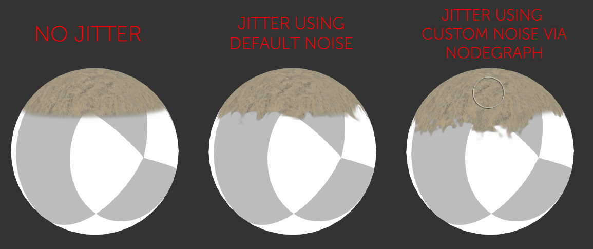
By default the Edge Blending Jitter (found in the Transform Tab of the Node) uses a node internal noise to perform its jittering/randomization of edges.
By attaching a noise of your choosing to the Jitter Noise Connection in the Nodegraph you can overwrite this
internal noise.
|
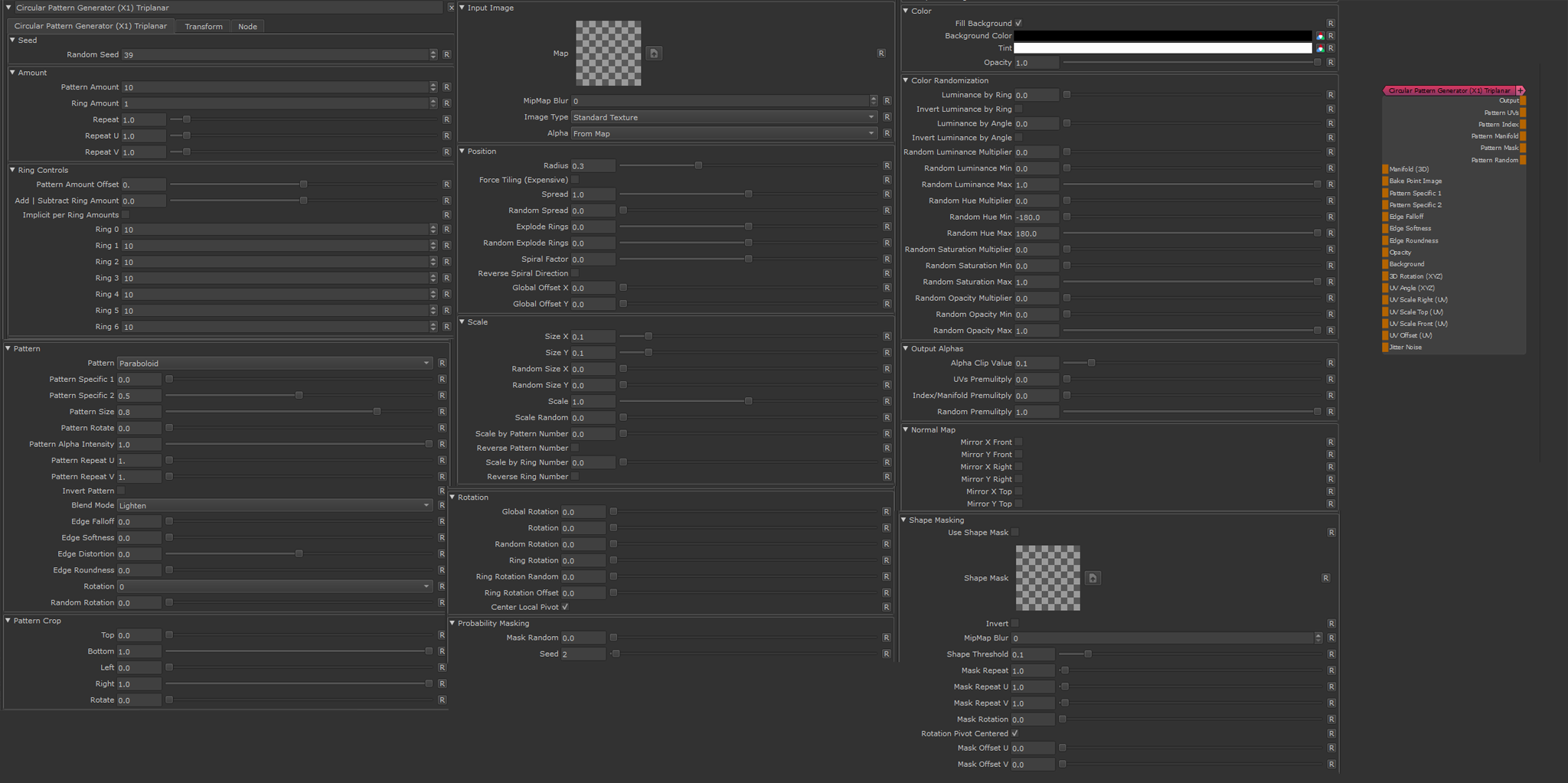
Node Properties |
MAIN TAB
- Seed
A value to randomize certain elements.
Some examples of randomization are Random Spread, Random Spacing etc.
- Pattern Amount
The absolute number of cells per ring
- Ring Amount
The absolute number of Rings to generate
- Repeat
The number of times to repeat the pattern. This is a very simple tiling operation and does not affect performance.
- Repeat U
The number of times to repeat the pattern horizontally. This gets multiplied with the Repeat and is a very simple tiling operation and does not affect performance.
- Repeat V
The number of times to repeat the pattern vertically. This gets multiplied with the Repeat and is a very simple tiling operation and does not affect performance.
The Ring Control Groups allows you to modify rings separately in order to not have the exact same amount of cells per ring.
- Pattern Amount Offset
A value to add or subtract from the Pattern Amount. This is basically the same as changing the Amount.
- Pattern Amount Offset per Ring
A value to add or subtract from the Pattern Amount per ring. This can help to have a less crowded appeareance to patterns in the center of the pattern.
- Add | Subtract Ring Amount
Subtracts the unique number of a ring from the Pattern Amount.
The final pattern amount for each ring is then
PatternAmount + (ring Number * Add|Subtract Ring Amount)
- Implicit per Ring Amounts
If on, the "Pattern Amount" in the "amount" group is ignored and each ring uses the fixed Amounts specified in the per-ring field (see below).
Pattern Amount offset and Add | Subtract Ring Amount are still evaluated
Example of implicit Pattern Amounts for different rings
- Ring 1 / 2 / /3 / /4 etc.
The Pattern Amount for the specific Ring Numbers to use, if Implicit per Ring Amount checkbox is on
- Pattern
Determines what pattern is used to fill each cell.
Options are
- A File Texture (Input Image)
Supply a Texture in the Input Image Section
- One of 23 procedurally generated Patterns
For a complete overview of all procedural patterns visit the Shape Node Help
- Pattern Specific 1
An Option to change the look of procedurally generated Patterns. Varies based on Patttern
|
|
This Setting has no effect if Input Image has been chosen under "Pattern" |
- Pattern Specific 2
An Option to change the look of procedurally generated Patterns. Varies based on Patttern
|
|
This Setting has no effect if Input Image has been chosen under "Pattern" |
- Pattern Size
Determines the size of the procedurally generated Pattern within a cell.
Please note this works together with any size/scale specified in the Size Group.
|
|
This Setting has no effect if Input Image has been chosen under "Pattern" |
- Pattern Rotate
Determines the rotation of the procedurally generated Pattern within a cell
|
|
This Setting has no effect if Input Image has been chosen under "Pattern" |
- Pattern Alpha Intensity
Determines the processing of the Alpha Channel of a procedurally generated pattern.
Example of reducing the Alpha Intensity from 1 to 0 on a large Hemisphere pattern
|
|
This Setting has no effect if Input Image has been chosen under "Pattern" |
- Pattern Repeat U
Repeats the pattern or input image x-amount of times horizontally in each cell.
Example of increasing Pattern Repeat U and V one after another

- Pattern Repeat V
Repeats the pattern or input image x-amount of times vertically in each cell.
Example of increasing Pattern Repeat U and V one after another
- Invert Pattern
Invert pattern or Input Image
- Blend Mode
The Blend Mode used to overlay a cell over other cells
Example of different effects achieved by changing the blend mode
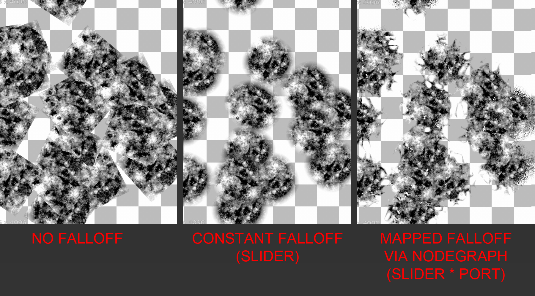
The Edge Controls give you control over the edge transparency of the generated pattern, allowing you to create 'Brush Effects'
- Edge Falloff
Will contract the edges of your loaded textures. This parameter can also be mapped via the Nodegraph
- Edge Softness
Will feather the edges of your loaded textures from the start of the Edge Falloff to the centre of your texture.
This parameter can also be mapped via the Nodegraph
- Edge Roundness
Switches the Falloff from Square (0.0) to Radial (1.0).
This parameter can also be mapped via the Nodegraph
- Edge Distortion
The Edge Distortion is distorting the alpha in the softened areas based on the luminance of the pattern.
If Edge Distortion is 1.0 black parts of the pattern inside the cell will be hidden in the area of Edge Softness.
If Edge Distortion is -1.0 white parts of the pattern inside the cell will be hidden in the area of Edge Softness.
Example of raising Edge Distortion from 0 to 1
- Rotation
Pre-rotates the Input Image or Pattern by either 90, 180 or 270 degrees
- Random Rotation
Applies a random rotation in 90 degree increments
The Pattern Crop options allow to 'cut' the edges of a patterns or input images, allowing even more variation
Example of using the Pattern Crop to generate a triangle from a square
- Top
Control the Crop from Top to Bottom per Shape
- Bottom
Control the Crop from Bottom to Top per Shape
- Left
Control the Crop from Left to Right per Shape
- Right
Control the Crop from Right to Left per Shape
- Rotate
Rotate the Crop 'Frame' around its center
- Map
Supply a texture map to use in the processing.
|
|
This setting is only evaluated if Pattern is set to 'Input Image' |
- Mipmap Blur
Allows you to blur the input image. This feature requires Mari 4.6v2.
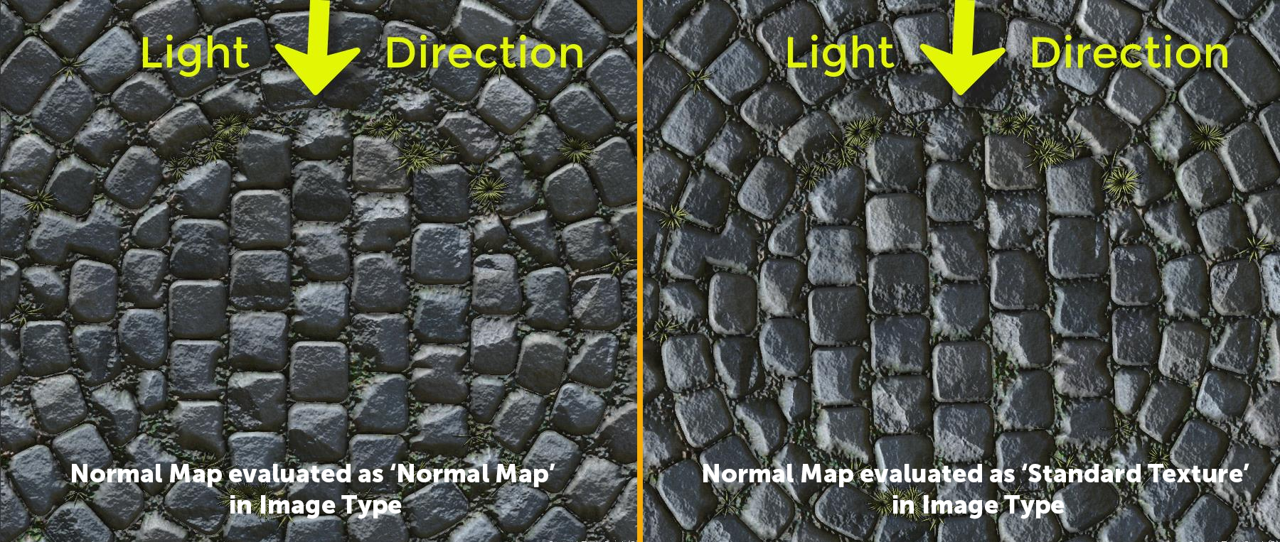
- Image Type
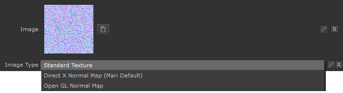
If an image is specified as a Normal Map, rotating images recalculates normal vectors for correct lighting results.
Below you can see an example of this. The Material and its normal map was rotated 90 degrees from its original output.
- With the Normal Map specified in the Image Type, Mari correctly recalculate the normal map vectors for rotation changes resulting in consistent lighting in viewport & render.
- If the Normal Map is treated as a 'Standard Texture', no normal orientation is recalcuated, resulting in incorrect lighting in viewport & render
- Alpha
Configure the Alpha Handling of the supplied image.
- From Map
The Transparency in your loaded texture map is used
- Alpha is Luminance
The Luminance of your loaded texture map is used as Alpha.
Black is transparent.
- Alpha is Inverted Luminance
The inverted Luminance of your loaded texture map is used as Alpha.
White is transparent.
- White
The Alpha of the loaded map is set to white resulting in the image being 100% opaque.
|
|
This setting is only evaluated if Pattern is set to 'Input Image' |
- Radius
Determines the Radius of the circular pattern
- Force Tiling (expensive)
Off by default, when on the calculation of the pattern will be completely tileable
|
|
WARNING: Force Tiling makes the node up to 8 times more expensive to calculate ! |
Examples of Force Tiling off (left) and Force Tiling on (right)
- Spread
Defines the distribution of the pattern in the 360 degrees of the circle

- Random Spread
Randomly distributes the pattern in the 360 degrees of the circle
- Explode Rings
Offsets the rings

- Random Explode Rings
Offsets the rings randomly. Affected by Random Seed
- Spiral Factor
Forces the pattern into a spiral

- Reverse Spiral Direction
Inverts the direction of the spiral
- Global Offset X/Y
Offsets the entire pattern in X or Y
- Size X/Y
Scales each Cell in X or Y

- Random SIze X/Y
Randomly scales the size in X or Y. Affected by Random Seed.
- Scale
Changes the scale of each cell uniformly
- Random Scale
Changes the scale of each cell randomly

- Scale by Pattern Number
Applies a scale factor based on the unique cell id. Lower cell id numbers receive higher scaling

- Reverse Pattern Number
Reverses the calculation for Scale by Pattern Number, meaning higher cell id numbers receive higher scaling
- Scale by Ring Number
Applies a scale factor based on the unique ring id. Lower cell id numbers receive higher scaling
- Reverse Ring Number
Reverses the calculation for Scale by Ring Number, meaning higher ring id numbers receive higher scaling
- Global Rotation
Rotates the entire pattern
- Local Rotation
Rotates each cell

- Random Rotation
Rotates each cell randomly. Affected by global seed.
- Ring Rotation
Very similar to Global Rotation, rotates each ring separately but not affected by
"Center Global Pivot"
- Random Ring Rotation
Rotates each ring randomly. Affected by global seed.
- Ring Rotation Offset
Rotates each ring while applying an angle offset per ring

- Center Global Pivot
Changes the Pivot for the "Global Rotation" option.
When on, the pivot is centered at each UDIM or at 0.5/0.5 (triplanar version).
When off the pivot is centered at the lower left corner (0.0 / 0.0)
- Center Local Pivot
Changes the Pivot for the Local Rotation option.
When on, the pivot is centered at each cells center.
When off the pivot is centered at the lower left corner of each cell
- Masking
Randomly hides pattern cells.
Affected by both global seed and seed below.
- Seed
Additional Seed affecting the "Masking" option.
This works together with the Global Seed option.
Shape Masking applies a mask to all cells of the Node. The Mask is applied in binary mode - a cell is either fully visible or hidden.
Other than for example using a Probability Mask attached to the Node Input Port, a Mask will never "cut through" a cell.
- Use Shape Mask
Activate Shape Mask Mode
- Shape Mask
The Image to use as Shape Mask
- MipMap Blur
A blur applied to the Shape Mask Image
- Shape Threshold
The value of the map representing the pivot point between "hidden" and "visible"
- Mask Repeat
THe number of times the Mask Image is repeated
- Mask Repeat U
The number of times the Mask Image is repeated horizontally. Multiplies against the "Mask Repeat"
- Mask Repeat V
The number of times the Mask Image is repeated vertically. Multiplies against the "Mask Repeat"
- Mask Rotation
Rotation of the Mask Image
- Rotation Pivot Centered
If on, rotation is evaluated against the center position (0.5 / 0.5) of the UVs.
If a 2D Node is used (as opposed to a triplanar node), this will mean a unique rotation pivot in the center of each udim.
- Mask Offset U/V
Translation values for the Mask in U and V
- Fill Background
If on, the background of the generated pattern will be filled with the background color
- Background Color
The color to fill the background with, if "Fill Background" is turned on. This color can be overwritten
via a Node Port
|
|
If using a procedural pattern, play around with the 'Alpha Intensity' in the Patter Group for best effects on a transparent background |
- Tint
A color or value to tint the result of the node with.
Tinting is performed before any color randomization and therefore can be used to apply color to other wise
gray scale patterns, after which color randomization can be applied.
Tinting is a multiplication operation.
- Opacity
The global Opacity of the Pattern. Can be overwritten via the Opacity Node Port.
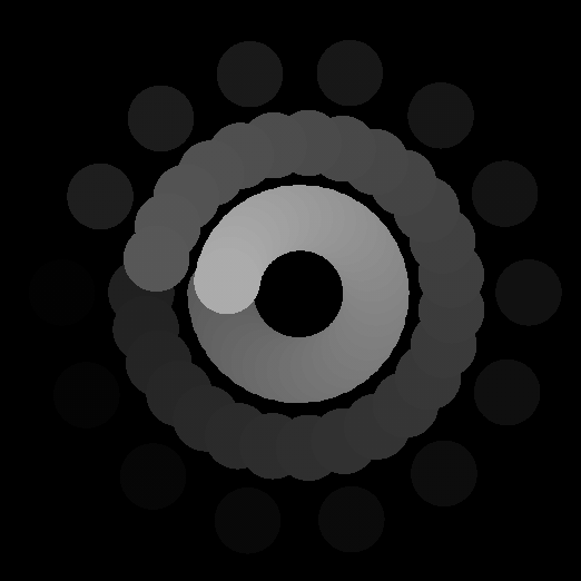
- Luminance by Ring
Applies an incremental luminance shift per ring of the generated pattern
- Invert Luminance by Ring
Inverts the order of Rings for the Luminance by Ring Operation
- Luminance by Angle
Applies an incremental luminance shift per slice of the generated pattern
- Invert Luminance by Angle
Inverts the order of slices for the Luminance by Angle Operation
- Random Luminance Multiplier
Affects how much the Luminance is randomized in between cells
- Random Luminance Min/Max
Sets the Min and Max Range for Random Luminance changes in between cells
- Random Hue Multiplier
Affects how much the Hue is randomized in between cells
- Random Hue Min/Max
Sets the Min and Max Range for Random Hue changes in between cells
- Random Saturation Multiplier
Affects how much the Saturation is randomized in between cells
- Random Saturation Min/Max
Sets the Min and Max Range for Random Saturation changes in between cells
- Random Opacity Multiplier
Affects how much the Opacity is randomized in between cells
- Random Opacity Min/Max
Sets the Min and Max Range for Random Opacity changes in between cells
The Settings found in the Output Alphas Group determine how transparency of cell content is treated in the additional Output Ports of the Node
(Pattern UVs, Pattern Index, Pattern Manifold and Pattern Random)
- Alpha Clip Value
The Alpha Clip Value determines the minimum value the alpha of the generated pattern is allowed to have.
Values below the clip value will automatically be set to 0.
This value can be useful to change if you are seeing slight artifacts around patterns.
The Alpha Clip Value will affect all Outputs.
- UVs premultiply
Premultiplies the transparency of cell content returned on the Pattern UVs output Port
- Index/Manifold premultiply
Premultiplies the transparency of cell content returned on the Pattern Index and Pattern Manifold output Ports
- Random premultiply
Premultiplies the transparency of cell content returned on the Pattern Random output Port
|
|
These options only apply, if the supplied input image is set to a normal map |
- Mirror X Front / Mirror Y Front
Will mirror the vectors of the normal map for the Front Projection Direction. This is useful to align the Normal Map correctly in space for your projection
- Mirror X Top / Mirror Y Top
Will mirror the vectors of the normal map for the Top Projection Direction. This is useful to align the Normal Map correctly in space for your projection
- Mirror X Right / Mirror Y Right
Will mirror the vectors of the normal map for the Right Projection Direction. This is useful to align the Normal Map correctly in space for your projection
TRANSFORM TAB
The Triplanar Settings control the projection of the texture in 3d space.
The settings are similar to a regular Triplanar Node found in Mari.
- 3D Scale
The 3D Scale controls the size of the Projection
- Projection Rotate X/Y/Z
Will change the rotation of the Triplanar 'Projection Cube' in space.
This should not be confused with changing UV Rotation which will rotate the projected image on
each side of the projection.
Projection Rotate is useful if your asset is not perfectly aligned in the main world space axis X Y and Z
and you see projection stretching as a result of it.
Sample of rotating a projection in 3d space. While this example is using
an Axis Projection Node the concept is the same for the Texture Scatter Triplanar Node
- Edge Falloff Start
The Edge Falloff Start determines the minimum angle where the projection
starts to be fully opaque
- Edge Falloff End
The Edge Falloff End determines the maximum angle where the projection
starts to be fully transparent
- Edge Falloff
The Edge Falloff Curve determines the general Falloff of each projection axis to its sides.
This is similar to adjusting the Edge Falloff Start and Edge Falloff End Sliders however
it allows you to create non-linear edge blending
Jitter will make the edges of projections less uniform/straight.
The Jitter Intensity determines the amplitude of the the Jitter.
You can overwrite the Noise used for jittering the edges by mapping the Jitter Noise Port in the Nodegraph
- Jitter Scale
Determines the Frequency of the internal Noise used for jittering.
|
|
Jitter Scale is ignored if something is attached via the Nodegraph to the Jitter Noise Port |
- Scale Right
Changes the UV Scale of the Right Side Projection
- U Scale Right
Will scale the UVs for the Right Side Projection along U (Horizontally)
- V Scale Right
Will scale the UVs for the Right Side Projection along U (Vertically)
- Scale Top
Changes the UV Scale of the Top Side Projection
- U Scale Top
Will scale the UVs for the Top Side Projection along U (Horizontally)
- V Scale Top
Will scale the UVs for the Top Side Projection along U (Vertically)
- Scale Front
Changes the UV Scale of the Front Side Projection
- U Scale Front
Will scale the UVs for the Front Side Projection along U (Horizontally)
- V Scale Front
Will scale the UVs for the Front Side Projection along U (Vertically)
Will rotate the result for all axis of the Triplanar Projection
- UV Rotation Right
Will rotate the UVs just along the X-Axis of the Triplanar Projection.
- UV Rotation Top
Will rotate the UVs just along the Y-Axis of the Triplanar Projection.
- UV Rotation Front
Will rotate the UVs just along the Z-Axis of the Triplanar Projection.
- U Offset
Will offset the result along U.
- V Offset
Will offset the result along V.