|
Tiled Infinity |
- Where to find it:
- Add Procedural Layer / Procedural / Extension Pack / Generators
 NodeGraph / Right Mouse Click / Add Nodes / Procedurals / Extension Pack / Generators
|
|
Infinity Tile is only available in Mari 4.6v2 or higher |
Infinity Tiling will apply a texture to the UVs based on a Hexadecimal Grid, with each Cell having a different sample point of the
original texture, hiding any repeating pattern when tiled.
The node will work best with input textures that have a chaotic appearance and does not work well with geometric shapes.
Comparison of the same Texture applied via a standard Tiled Node vs the new Tiled Infinity Node
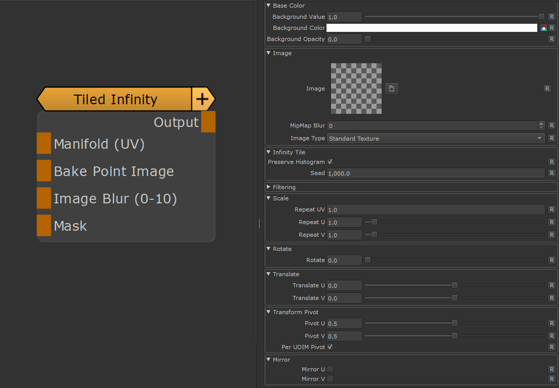
- Manifold (UV)
The 'Manifold' connection can be used to feed in a coordinate system to evaluate the Image on.
Possible Nodes to attach to are 'UV' & 'Manifold UV' for example to adjust the tiling of the image
- Bake Point Image
![]()
The Bake Point Image Port allows you to feed in data from upstream nodes that has been baked via a bake point into the Node.
When the node is evaluated, the Bake Point attached to the Port will be sampled and the UDIM 1001 Image will be transferred into
the Image Attribute of the Node.
This allows you to create patterns and textures via a nodegraph and use them directly inside this node with an element of non-destructivness
Example of using a Nodegraph and a Bake Point to dynamically feed a Pattern Generator Node with Node Inputs
- Mask
The Mask allows you to change the opacity of areas of your Image
- Image Blur (0-10)
The Image Blur Port allows you to control the blurring of Node's Image via a node stream.
The value range of the fed in Node stream needs to be between 0 and 10.
The Mip Map Blur Setting below the Image Attribute inside of the Node's Properties gets added on top of the fed in value.
MAIN TAB
It is possible to define a background color for this node. Transparent areas of the node will be filled with the Background Value/Color
if the Background Opacity is set to 1.0.
If no Image is set in the Image attribute the computation of the Node will default to a lightweight, performance friendly method that only
evaluates the background.
- Background Value
Defines the grayscale Background value of the Projection.
|
|
The Background Value is multiplied against the Background color, so to only use the Value field, set the Background color to white |
- Background Color
Defines a Background Color for the Projection. This can help to eliminate semi-transparent areas of your projection, caused by the mesh normals
not being aligned with the projection
|
|
The Background Color is multiplied against the Background value, so to only use the Color field, set the Background value to 1.0 |
- Background Opacity
Defines if the Projection is filled by default with the Background Color / Background Value
|
Image |
- Image
Drag & Drop an image from the image manager or outside of Mari or use the Browse Button
to browse for one.
- Mipmap Blur
Allows you to blur the input image. This feature requires Mari 4.6v2.
Blurring can also be controlled via the Image Blur Port of the Node.
|
|
If an input is attached to the Image Blur Port of the Node, the value of the Mipmap Blur slider and the Image Blur Port Input will be added together. |
- Image Type
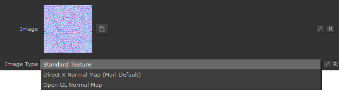
If an image is specified as a Normal Map, rotating images recalculates normal vectors for correct lighting results.
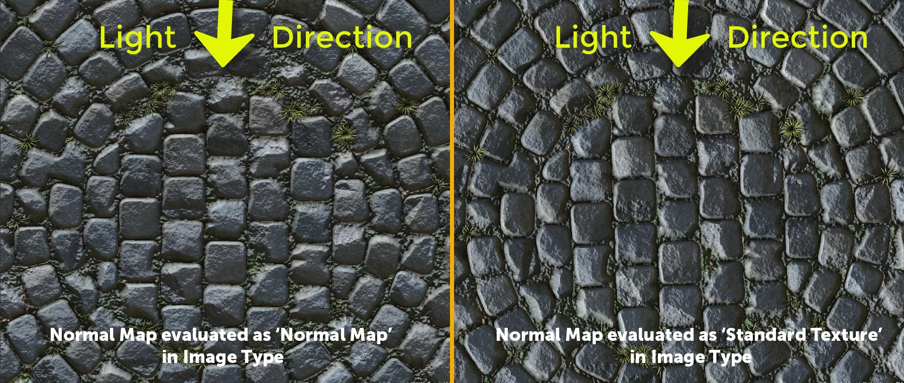
Below you can see an example of this. The Material and its normal map was rotated 90 degrees from its original output.
- With the Normal Map specified in the Image Type, Mari correctly recalculate the normal map vectors for rotation changes resulting in consistent lighting in viewport & render.
- If the Normal Map is treated as a 'Standard Texture', no normal orientation is recalcuated, resulting in incorrect lighting in viewport & render
|
Infinity Tile |
- Preserve Histogram
If on, the original contrast ratio of the source image will be restored and applied to the result
- Patch Tex Scale
The Area each Sample Point covers within the Source Texture
- Seed
Allows you to create randomize the result
- Filter Image
The Filtering Method used for the loaded Image
- Anisotropy
If the Filter Method is set to 'Anisotropic' this will determine the amount of filtering when the image is
viewed at grazing angles
- Repeat UV
A global multiplier on the 'Repeat U' and Repeat V' Sliders
- Repeat U
Sets the Repeat along the U coordinate (horizontal) multiplied by the 'Repeat UV'
- Repeat V
Sets the Repeat along the V coordinate (vertical) multiplied by the 'Repeat UV'
- Rotate
Will apply a rotation to the UVs around the centre of them (u = 0.5,v = 0.5)
- Translate U / V
Will translate your UVs along U (horizontal) or V (vertical)
The Transform Pivot determines the pivot used for any UV Transformation such as Scaling and Rotating
- Pivot U / V
When perUDIMPivot is turned on this determines the location of the Pivot for each UDIM. A value of 0.5/0.5 means that
each UDIM has its Transform Pivot in the centre of the Patch.
This is comparable the Transform Pivot you might be familiar with when applying Layer Transformations in Photoshop.
This setting is not evaluated when PerUDIM Pivot is turned off.
![]()
- Per UDIM Pivot
Affects the transformation pivot for UV Transforms.
With PerUDIMPivot on,all transformation will be performed with a pivot inside each UDIM (as determined by the Pivot U/V Position).
With PerUDIMPivot off, transformations for all UDIMs share one common pivot at the base of UDIM 1001
This will ensure seamless textures across UDIMs when your UV Shell is scaled up and covering multiple UDIMs.
without a cut inbetween.
UV Transformations applied to multiple UDIMs with perUDIM Pivot On (left) and off (right)

- Mirror U
Will mirror your UVs along U (horizontal)
- Mirror V
Will mirror your UVs along V (vertical)