|
Shape Triplanar by Jens Kafitz |
- Where to find it:
- Add Procedural Layer / Procedural / Extension Pack / Pattern /
 NodeGraph / Right Mouse Click / Add Nodes / Procedural / Extension Pack / Pattern /
|
|
This Node is also available as a 2D Version |
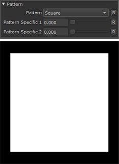
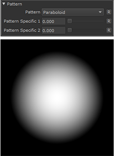
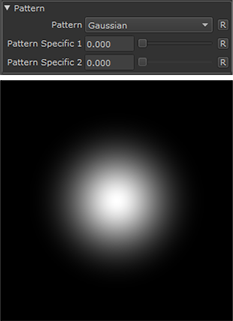
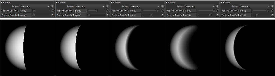
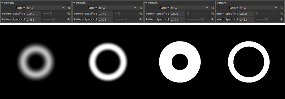
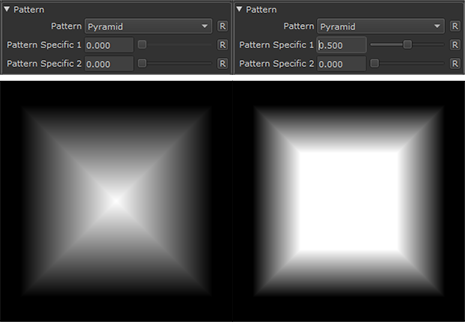
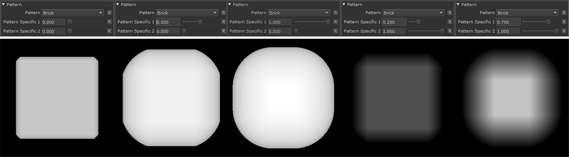
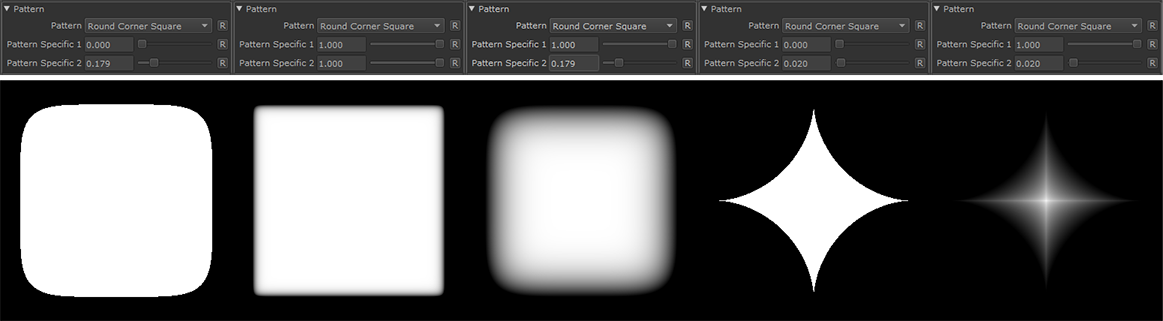
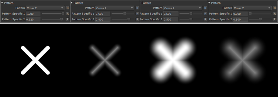
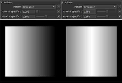
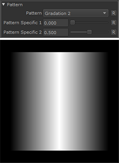
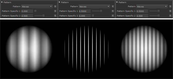
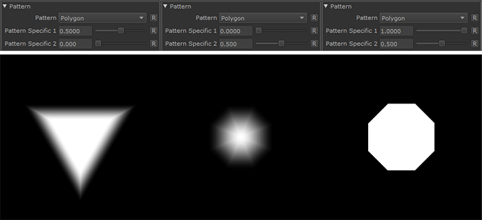
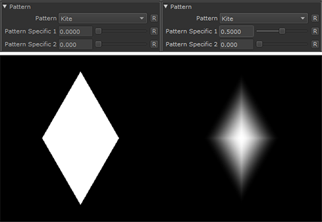
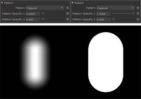
The Shape Node allows you to generate a large variety of standard shapes
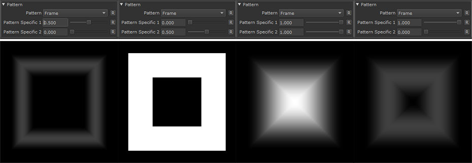
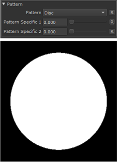
Below you can see an overview over the separate shape types with their two modifiers.
|
|
Pattern Specific Options are not configurable for all shapes. |
|
Square |
|
Frame |
|
Disc |
|
Paraboloid |
|
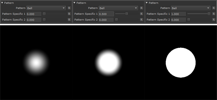
Bell |
|
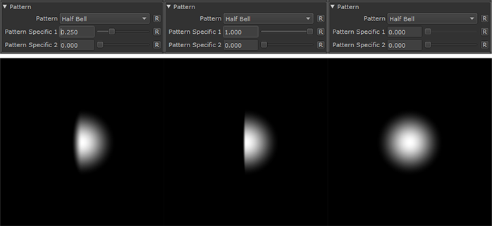
Half Bell |
|
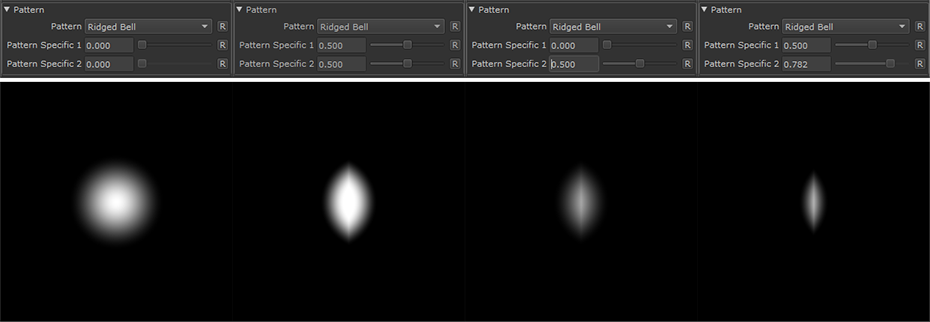
Ridged Bell |
|
Gaussian |
|
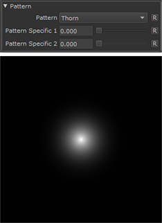
Thorn |
|
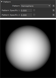
Hemisphere |
|
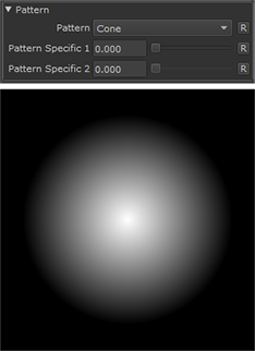
Cone |
|
Crescent |
|
Ring |
|
Pyramid |
|
Brick |
|
Round Corner Square |
|
Cross |

|
Cross 2 |
|
Gradation |
|
Gradation 2 |
|
Waves |
|
Polygon |
|
Kite |
|
Capsule |
|
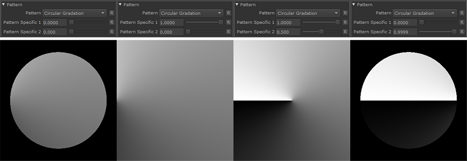
Circular Gradation |
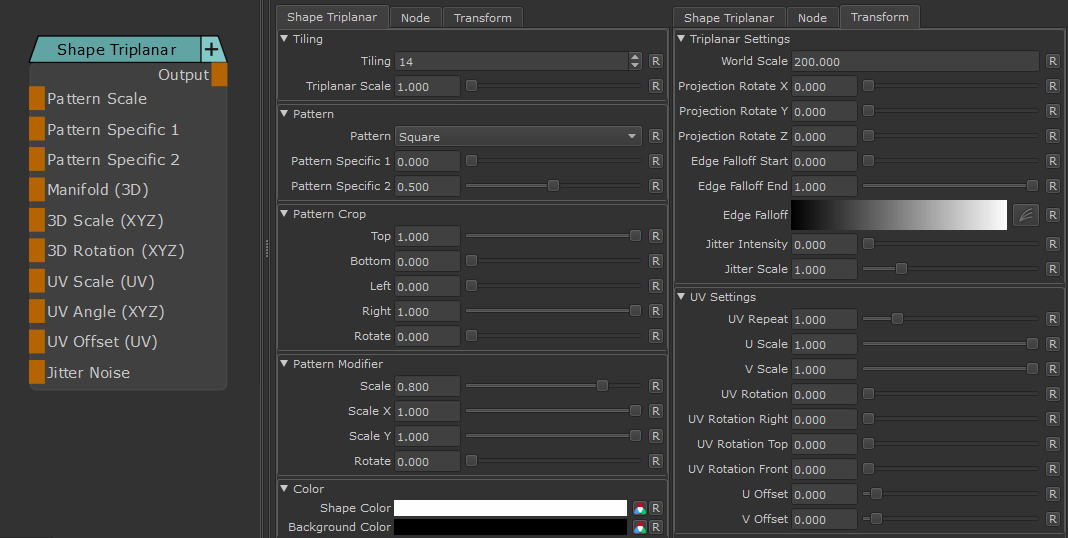
- Manifold 3D
When mapped the world space position the node uses to calculate the projection is supplied by the port.
This can be used for example to apply warping to the projection using Manifold Nodes
- Pattern Scale
Control the Size of the generated Pattern. Overwrites Scale Slider if mapped
- Pattern Specific 1
An Option to change the look of the generated Pattern. Varies based on Patttern. Overwrites Pattern Specific 1 Slider if mapped.
- Pattern Specific 2
An Option to change the look of the generated Pattern. Varies based on Patttern. Overwrites Pattern Specific 2 Slider if mapped
- Manifold 3D
When mapped the world space position the node uses to calculate the projection is supplied by the port.
This can be used for example to apply warping to the projection using Manifold Nodes
- Manifold 3D
When mapped the world space position the node uses to calculate the projection is supplied by the port.
This can be used for example to apply warping to the projection using Manifold Nodes
- 3D Scale (XYZ)
When mapped
- the red channel of the attached connection is used to drive the 3D Scale Attribute for the front part of the projection.
- The green channel of the attached connection is used to drive the 3D Scale Attribute for the top part of the projection.
- The blue channel of the attached connection is used to drive the 3D Scale Attribute for the right part of the projection.
- 3D Rotation (XYZ)
When mapped the red channel of the attached connection is used to drive the Rotate X Attribute,
the green channel the Rotate Y Attribute and the blue channel the Rotate Z Attribute
- UV Scale (UV)
When mapped the red channel of the attached connection is used to drive the UV Angle X Attribute,
the green channel the UV Angle Y Attribute and the blue channel the UV Angle Z Attribute
- UV Angle (XYZ)
When mapped the red channel of the attached connection is used to drive the UV Rotation Right Attribute,
the green channel the UV Rotation Top Attribute and the blue channel the UV Rotation Front Attribute
- UV Offset (UV)
When mapped the red channel of the attached connection is used to drive the U Offset Attribute,
the green channel the V Offset Attribute
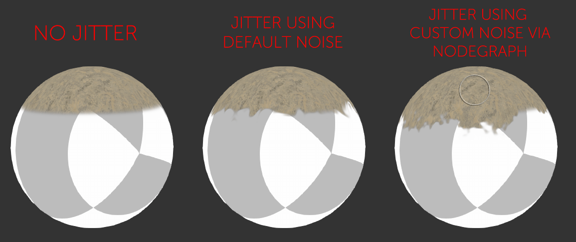
By default the Edge Blending Jitter uses a node internal noise to perform its jittering/randomization of edges.
By attaching a noise of your choosing to the Jitter Noise Connection in the Nodegraph you can overwrite this
internal noise.
MAIN TAB
- Tiling
Control the repeat of the generated shape
- Pattern
Select the shape type to generate
- Pattern Specific 1
An Option to change the look of the generated Pattern. Varies based on Patttern
- Pattern Specific 2
An Option to change the look of the generated Pattern. Varies based on Patttern
|
|
Try using the Arrow up and down keys to easily control and change Pattern specific values |
The Pattern Crop options allow to 'cut' the edges of a pattern, allowing even more variation
Example of using the Pattern Crop to generate a triangle from a square
- Top
Control the Crop from Top to Bottom per Shape
- Bottom
Control the Crop from Bottom to Top per Shape
- Left
Control the Crop from Left to Right per Shape
- Right
Control the Crop from Right to Left per Shape
- Rotate
Rotate the Crop 'Frame' around its center
- Scale
Control the Size of the generated Pattern
|
|
You can enter values outside the slider range via the keyboard |
- Scale X
A multiplier against the horizontal Size of the Pattern
|
|
You can enter values outside the slider range via the keyboard |
- Scale Y
A multiplier against the vertical Size of the Pattern
|
|
You can enter values outside the slider range via the keyboard |
- Rotate
Rotate the generated pattern
- Shape Color
The Fill Color of the generated Shape
- Background Color
The Background Color of the Shape
TRANSFORM TAB
The Triplanar Settings control the projection in 3d Space
The settings are similar to a regular Triplanar Node found in Mari.
- 3D Scale
Will increase the size of the projection.
This is a very similar effect to changing the UV Repeat in the UV Settings.
- Projection Rotate X/Y/Z
Will change the rotation of the Triplanar 'Projection Cube' in space.
This should not be confused with changing UV Rotation which will rotate the projected image on
each side of the projection.
Projection Rotate is useful if your asset is not perfectly aligned in the main world space axis X Y and Z
and you see projection stretching as a result of it.
Sample of rotating a projection in 3d space. While this example is using
an Axis Projection Node the concept is the same for the Texture Scatter Triplanar Node
- Edge Falloff Start
The Edge Falloff Start determines the minimum angle where the projection
starts to be fully opaque
- Edge Falloff End
The Edge Falloff End determines the maximum angle where the projection
starts to be fully transparent
- Edge Falloff
The Edge Falloff Curve determines the general Falloff of each projection axis to its sides.
This is similar to adjusting the Edge Falloff Start and Edge Falloff End Sliders however
it allows you to create non-linear edge blending
Jitter will make the edges of projections less uniform/straight.
The Jitter Intensity determines the amplitude of the the Jitter.
You can overwrite the Noise used for jittering the edges by mapping the Jitter Noise Port in the Nodegraph
- Jitter Scale
Determines the Frequency of the internal Noise used for jittering.
|
|
Jitter Scale is ignored if something is attached via the Nodegraph to the Jitter Noise Port |
Will repeat the result x-amount of times.
- U Scale
Will scale the result along U.
- V Scale
Will scale the result along V.
Will rotate the result for all axis of the Triplanar Projection
- UV Rotation Right
Will rotate the UVs just along the X-Axis of the Triplanar Projection.
- UV Rotation Top
Will rotate the UVs just along the Y-Axis of the Triplanar Projection.
- UV Rotation Front
Will rotate the UVs just along the Z-Axis of the Triplanar Projection.
- U Offset
Will offset the result along U.
- V Offset
Will offset the result along V.