|
Manifold UV by Jens Kafitz |
- Where to find it: (This Node is available in the Nodegraph only)
 NodeGraph / Right Mouse Click / Add Nodes / Manifold /
Manifold UV is used to change scale, offset and rotation of 2D Coordinates (UV Coordinates).
All Extension Pack Procedurals have a 'Manifold' connection in the Nodegraph to attach this to.
Standard Mari Nodes if supported have a 'UV' connection that is compatible, although Nodes with
a 'Position' Input work as well.
When attaching a Manifold UV node to another node, the target node will be evaluated in UV Space instead of
its default Space. The behavior is the same as checking the 'UV Space' Checkbox in a Extension Pack Procedural
but the Manifold UV Node can be used to modify multiple Nodes at once.
'Manifold UV' by default uses your objects UV Coordinates.
Scale, Rotation and Offset of Coordinates are exposed as parameters in the Nodegraph, allowing you to
optionally drive them by another Node if needed
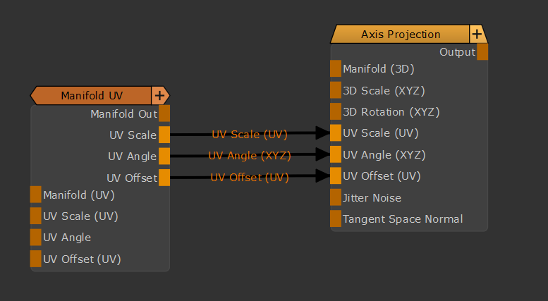
- Manifold Out
The Default Output of the combined Manifold Processing.
Can be for example connected to any Manifold (UV) or UV input on other nodes.
- UV Scale
Outputs only the Scaling Component of the Manifold
- UV Angle
Outputs only the Angle Component of the Manifold
- UV Offset
Outputs only the Translation Component of the Manifold
UV Scale, Angle and Offset can for example be used to drive the UV Scale, Angle and Offset on Triplanar Nodes:
- Manifold (UV)
When this connection is mapped in the Nodegraph it will overwrite the coordinate system used by the Node.
By default, if the 2D Coordinates Handle is unmapped the Node will use your Objects UV Data.
You can for example attach a 'UV' Node here or even another Manifold Node (Manifold UV, Manifold by Locator etc.)
- UV Scale (UV)
When this connection is mapped in the Nodegraph it will overwrite the Nodes Sliders in the 'Transform Scale'
Group. You can attach any node to the Scale Handle and drive U and V by modifying the incoming RG(B)
Data (R = U, G = V, B = not used)
- UV Angle
When this connection is mapped in the Nodegraph it will overwrite the Nodes Sliders in the 'Transform Rotate'
Group. You can attach any node to the Rotation Handle and drive U and V by modifying the incoming RG(B)
Data. Rotation is a 360 Degree Field so you need to modify the 'Intensity' of incoming values to get correct
degree numbers.
- UV Offset (UV)
When this connection is mapped in the Nodegraph it will overwrite the Nodes Sliders in the 'Transform Translate'
Group. You can attach any node to the Translation Handle and drive U and V by modifying the incoming RG(B)
Data (R = U, G = V, B = not used)
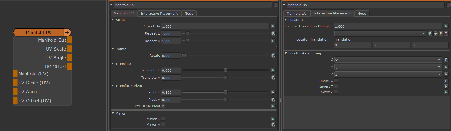
MAIN TAB
- Repeat UV
A global multiplier on the 'Repeat U' and Repeat V' Sliders
- Repeat U
Sets the Repeat along the U coordinate (horizontal) multiplied by the 'Repeat UV'
- Repeat V
Sets the Repeat along the V coordinate (vertical) multiplied by the 'Repeat UV'
- Rotate
Will apply a rotation to the UVs around the centre of them (u = 0.5,v = 0.5)
- Translate U / V
Will translate your UVs along U (horizontal) or V (vertical)
The Transform Pivot determines the pivot used for any UV Transformation such as Scaling and Rotating
- Pivot U / V
When perUDIMPivot is turned on this determines the location of the Pivot for each UDIM. A value of 0.5/0.5 means that
each UDIM has its Transform Pivot in the centre of the Patch.
This is comparable the Transform Pivot you might be familiar with when applying Layer Transformations in Photoshop.
This setting is not evaluated when PerUDIM Pivot is turned off.
![]()
- Per UDIM Pivot
Affects the transformation pivot for UV Transforms.
With PerUDIMPivot on,all transformation will be performed with a pivot inside each UDIM (as determined by the Pivot U/V Position).
With PerUDIMPivot off, transformations for all UDIMs share one common pivot at the base of UDIM 1001
This will ensure seamless textures across UDIMs when your UV Shell is scaled up and covering multiple UDIMs.
without a cut inbetween.
UV Transformations applied to multiple UDIMs with perUDIM Pivot On (left) and off (right)

- Mirror U
Will mirror your UVs along U (horizontal)
- Mirror V
Will mirror your UVs along V (vertical)
INTERACTIVE PLACEMENT TAB
- Locator Translation Multiplier
UV Modifications are a 2D Process while Locator Movement in the Viewport is a 3D Process.
Moving your Locator a certain distance in the viewport might result in a faster or slower UV move than you are happy with.
The Locator Translation Multiplier is a multiplier against the distance you moved your locator in the viewport allowing you to fine tune
how much the UVs 'stick' to a locator movement.
|
|
By default your objects bounding boxes are used as a base for computation of movement. |
- Locator Translation
Allows you to pick or create a Locator for Translation so you can adjust the Manifold Transformations directly in the viewport.
Refer to the Locator Usage Section of the Manifold by Locator Node or the Locator Video above for samples.
- X / Y / Z
Determines the mapping of each axis of the locator in the viewport to the node internal coordinate system.
UV Modifications are a 2D Process however the Locator movement in the viewport is a 3D Process.
Your UVs might rotated or your object's faces are aligned in the viewport in a way the default interpretation of a Locator Axis might not
correspond with your actual UVs anymore.
In these cases it might be necessary to change to the Axis mapping in order for Locator Modifications in the Viewport to affect the UVs in a more intuitive way.
- Invert X / Y / Z
Will invert the selected Axis. This can be useful for example in case of rotated UVs where a viewport locator move upwards moves the uvs downwards.