Axis Projection by Jens Kafitz |
Axis Projection Array is a modification of the Extension Pack Axis Projection Node which is similar to a Triplanar projection but gives more control over projection orientation by isolating the positive & negative part of each axis.
In addition it allows you to rotate all axis globally for cases where your object is not perfectly aligned in X, Y and Z.
This 'Array' Variant of the Node allows simultaneous Projection of up to 6 Images via a single node making it ideal for projecting an entire material
at once.
When mapped the red channel of the attached connection is used to drive the World Scale Attribute
When mapped the red channel of the attached connection is used to drive the UV Angle X Attribute,
the green channel the UV Angle Y Attribute and the blue channel the UV Angle Z Attribute
When mapped the red channel of the attached connection is used to drive the UV Angle X Attribute,
the green channel the UV Angle Y Attribute and the blue channel the UV Angle Z Attribute
When mapped the red channel of the attached connection is used to drive the UV Angle X Attribute,
the green channel the UV Angle Y Attribute and the blue channel the UV Angle Z Attribute
When mapped the red channel of the attached connection is used to drive the Rotate X Attribute,
the green channel the Rotate Y Attribute and the blue channel the Rotate Z Attribute
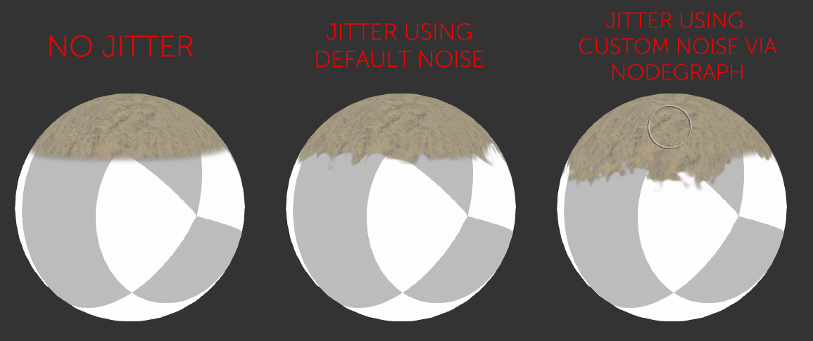
By default the Edge Blending Jitter uses a node internal noise to perform its jittering/randomization of edges.
By attaching a noise of your choosing to the Jitter Noise Connection in the Nodegraph you can overwrite this
internal noise.
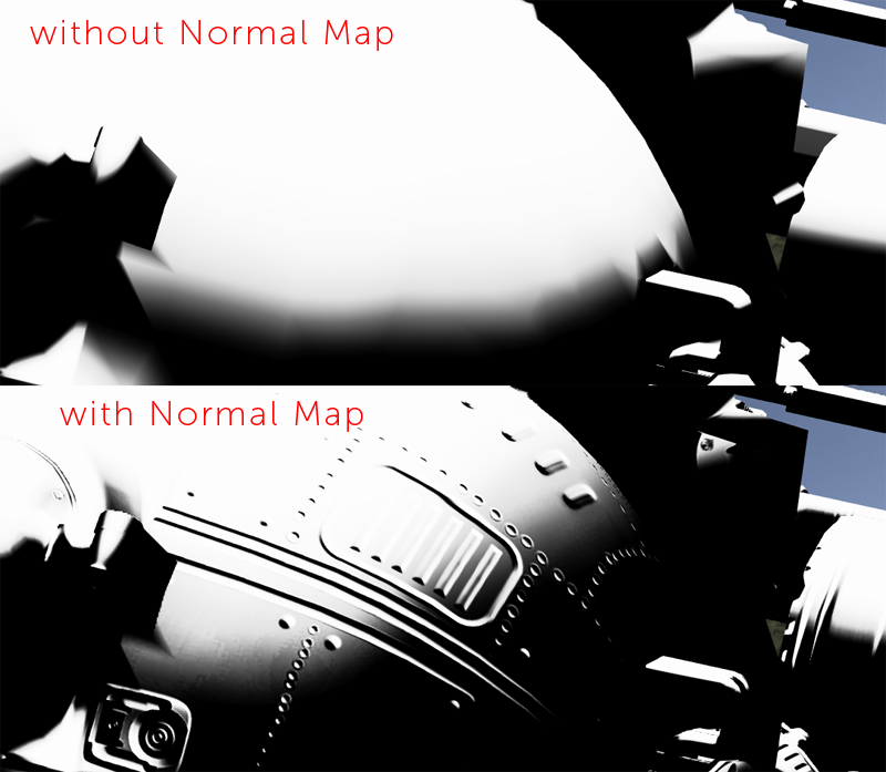
The Node Graph 'Tangent Space Normal' Handle allows you to have the Axis Projection evaluated against the effects of a
normal map as well
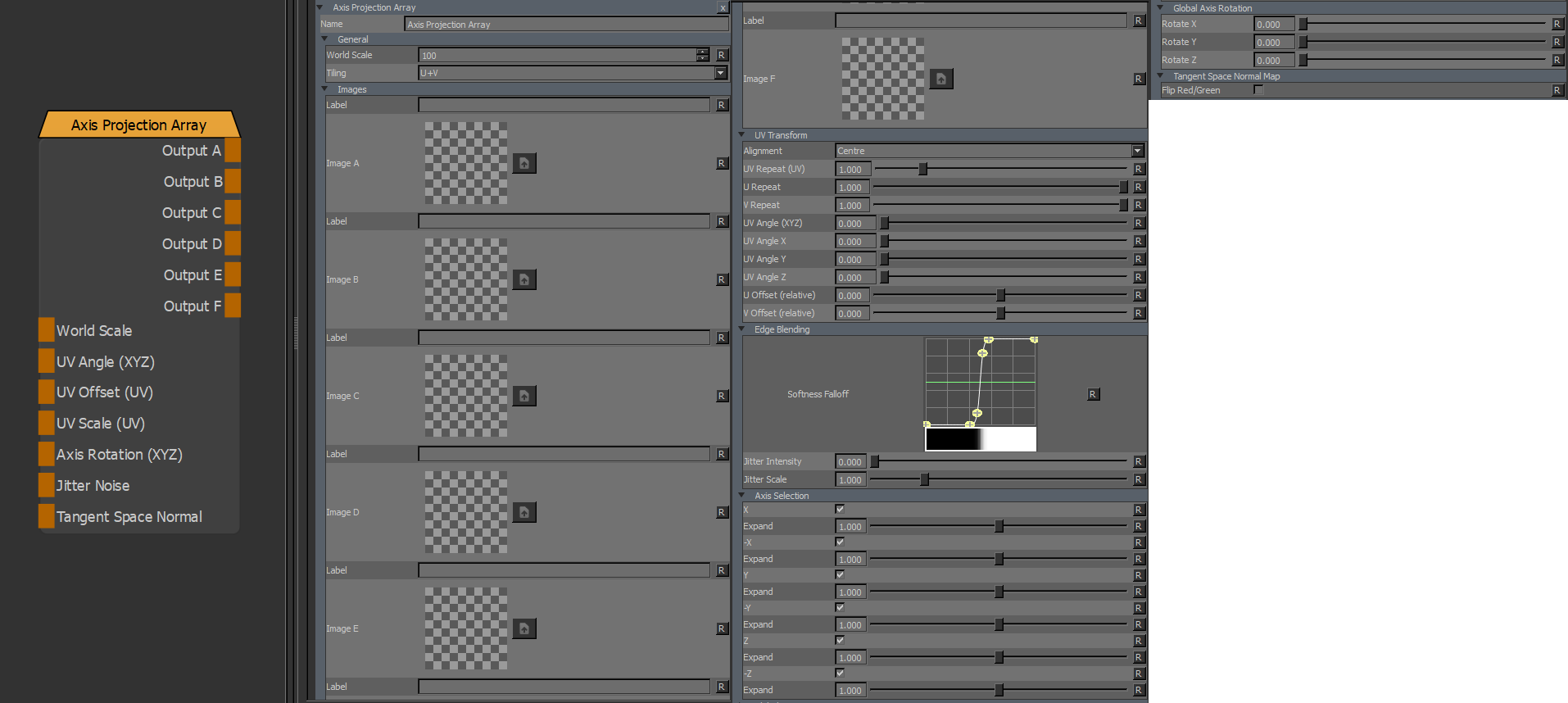
The Output from each Image slot
World Scale is a global scale multiplier on all options allowing you to uniformly scale up the projection
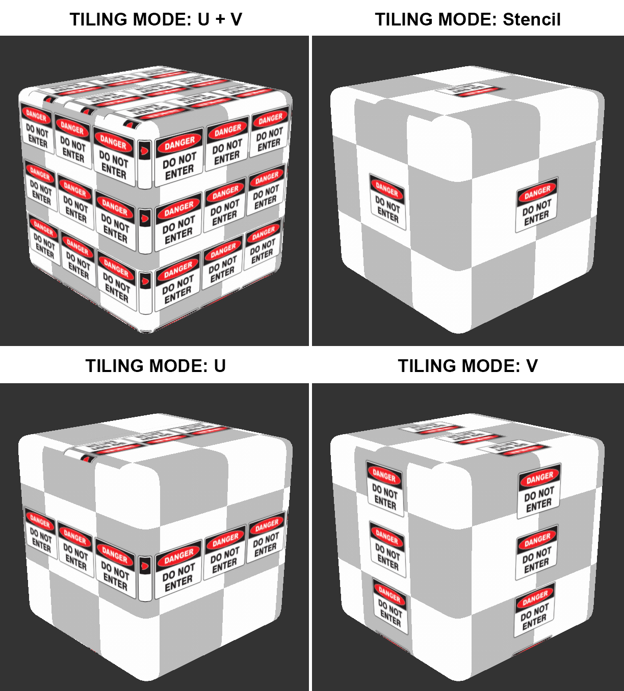
Determines the Tiling Mode of the Projection
A Text field for each Image to add a description
6 Image Fields to fill with Projection Images
UV Transform |
Determines the default Position the Projecion is oriented on, in relation to your object's bounding box:
A uniform repeat on u + v of your image.
This is also exposed as a port in the Nodegraph named UV Scale (UV)
The repeat along U. Multiplied against the UV Repeat (UV) attribute.
The repeat along V. Multiplied against the UV Repeat (UV) attribute.
A uniform Angle to rotate your projection image.
This is applied to all directions of the Projection.
The Rotational Pivot is the center of your object
If Stencil Mode is on, the Rotational Pivot shifts to the center of your image
Angle to rotate your projection image in the X/-X Axis of your Projection.
Multiplied against the UV Angle Attribute.
This is also exposed as a port in the Nodegraph named UV Angle (XYZ)
meaning the red channel of any attached Node is used to drive the UV Angle X Attribute
The Rotational Pivot is the center of your object
If Stencil Mode is on, the Rotational Pivot shifts to the center of your image
Angle to rotate your projection image in the Y/-Y Axis of your Projection.
Multiplied against the UV Angle Attribute.
This is also exposed as a port in the Nodegraph named UV Angle (XYZ)
meaning the green channel of any attached Node is used to drive the UV Angle Y Attribute
The Rotational Pivot is the center of your object
If Stencil Mode is on, the Rotational Pivot shifts to the center of your image
Angle to rotate your projection image in the Z/-Z Axis of your Projection.
Multiplied against the UV Angle Attribute.
This is also exposed as a port in the Nodegraph named UV Angle (XYZ)
meaning the blue channel of any attached Node is used to drive the UV Angle Z Attribute
The Rotational Pivot is the center of your object
If Stencil Mode is on, the Rotational Pivot shifts to the center of your image
Offset along the X Axis of your Image.
This is also exposed as a port in the Nodegraph named UV Offset (UV)
meaning that the red channel of any attached Node is used to drive the U Offset Attribute
If Stencil Mode is on, the Offset is evaluated for the entire projection plane instead of based on the
width of the projected image
Offset along the Y Axis of your Image
This is also exposed as a port in the Nodegraph named UV Offset (UV)
meaning that the green channel of any attached Node is used to drive the V Offset Attribute
If Stencil Mode is on, the Offset is evaluated for the entire projection plane instead of based on the
width of the projected image
The Softness Falloff Curve determines the general Falloff of each projection axis to its sides.
|
Fully opaque projection by default Different from the Triplanar Projection, the default Curve together with default 'Expand' settings will result in a completely opaque projection when all axis directions are turned on. |
Jitter will make the edges of projections less uniform/straight.
The Jitter Intensity determines the amplitude of the the Jitter.
You can overwrite the Noise used for jittering the edges by mapping the Jitter Noise Port in the Nodegraph
Determines the Frequency of the internal Noise used for jittering.
|
Jitter Scale is ignored if something is attached via the Nodegraph to the Jitter Noise Port |
Projects the Image from the positive and/or negative world X Axis
Expand will broaden the area of influence of each axis.
This can cause texture stretching if pushed too far.
Projects the Image from the positive and/or negative world Y Axis
Expand will broaden the area of influence of each axis.
This can cause texture stretching if pushed too far.
Projects the Image from the positive and/or negative world Z Axis
Expand will broaden the area of influence of each axis.
This can cause texture stretching if pushed too far.
|
Expand Axis Changing the 'Expand' Parameter under each Axis will expand the influence of the axis. Please note this can cause texture stretching if pushed too far.
|
Allows you to rotate the global X, Y and Z axis separately to best suite your models need.
This is also exposed as a port in the Nodegraph called Axis Rotation (XYZ) meaning that
the red channel of an attached Node is used to drive the Rotate X Attribute, the green channel
to drive the Rotate Y Attribute and the blue channel to drive the Rotate Z attribute.
Allows you to flip the Red/Green Component of a Tangent Space Normal Map attached to the Node in the
Nodegraph
Created with the Personal Edition of HelpNDoc: Free Kindle producer